

Understanding the flow through a turbomachine requires connecting the aerodynamic behavior of individual blade passages with the redistribution of fluid throughout the machine. Two-dimensional cascade analysis explains how blades turn the flow, generate aerodynamic forces, and introduce losses. Three-dimensional analysis extends this understanding to radial equilibrium, spanwise variations, secondary flows, and the interaction between blade rows. Together, these approaches provide the physical foundation for numerical turbomachinery analysis, from simplified throughflow methods to detailed CFD simulations.
This chapter brings together four closely related subjects: two-dimensional blade cascades, three-dimensional flow-field analysis, non-reflecting boundary conditions, and throughflow analysis using Ansys Vista TF. The central challenge is understanding how much of the real flow physics can be represented using simplified models, and when the additional complexity of three-dimensional CFD becomes necessary.
1. Why turbomachinery flow is difficult to model
Flow inside compressors, turbines, and pumps is inherently three-dimensional. The fluid travels through curved passages, changes direction, accelerates or decelerates, and interacts with both rotating and stationary blades. Pressure gradients develop in several directions, while boundary layers, wakes, shocks, and secondary flows introduce additional complexity.
A complete CFD simulation can resolve much of this behavior, but it requires detailed geometry, a suitable computational mesh, appropriate physical models, and significant computational resources.
Fortunately, turbomachines have an important geometric characteristic: their blades are arranged in repeating rows. This periodicity allows the complete flow field to be decomposed into simpler problems.
Two complementary descriptions are particularly useful.
Blade-to-blade analysis examines the flow between neighboring blades. It describes the turning of the fluid, the pressure distribution around the profiles, and the aerodynamic losses generated within a passage.
Meridional analysis examines the flow in a plane containing the machine axis and radial direction. It describes how the fluid moves through the annulus and how velocity, pressure, and other properties vary between the hub and casing.
These descriptions are closely related. Blade-to-blade calculations determine how the blades influence the flow, while meridional calculations describe how that flow is distributed throughout the machine.
This separation forms the basis of quasi-three-dimensional methods, often called Q3D methods. They approximate a complex three-dimensional problem by combining simpler two-dimensional descriptions.
The approximation is especially useful during preliminary design, when many blade geometries and operating conditions must be evaluated before committing to expensive CFD simulations.
2. Two-dimensional blade cascades
2.1 The cascade concept
A blade cascade is a periodic arrangement of aerodynamic profiles representing a row of turbomachinery blades.
In an axial machine, imagine selecting a cylindrical surface at a constant radius and unwrapping it into a flat plane. The curved arrangement of blades becomes a linear sequence of aerodynamic profiles.
Under suitable assumptions, the flow through each passage is identical to the flow through its neighboring passages. Instead of simulating the entire blade row, it is therefore possible to simulate a single passage with periodic boundaries.
This idealization requires the flow to be approximately two-dimensional on the selected surface, with negligible variations in the radial direction.
The numerical domain contains one blade passage, with an inlet upstream, an outlet downstream, and two periodic boundaries connecting equivalent locations in neighboring passages.
The periodic boundaries reproduce the behavior of an effectively infinite row of blades.
This approach greatly reduces computational cost while preserving the essential aerodynamic interaction between neighboring profiles.
A cascade is not simply an isolated airfoil repeated several times. Neighboring blades modify the pressure and velocity fields around each other. Their spacing, orientation, and geometry influence the aerodynamic behavior of the entire row.
2.2 Linear and annular cascades
Two configurations are commonly used in experimental and numerical investigations.
A linear cascade consists of a straight row of identical blades. Its geometry is characterized by blade chord, spacing, span, and the number of blades. Linear cascades are particularly useful for studying the aerodynamic behavior of blade sections under controlled conditions.
An annular cascade arranges blades around a circular passage. This configuration more closely represents the geometry of an actual axial turbomachine and introduces radial position as an additional geometric parameter.
Linear cascades are generally more convenient for developing aerodynamic correlations, while annular cascades are valuable when studying specific blade rows or scaled machine configurations.
The distinction matters because the ideal two-dimensional behavior of a linear cascade becomes more difficult to reproduce when radial pressure gradients, endwall boundary layers, and three-dimensional effects become important.
2.3 Experimental cascade testing
Cascade experiments provide much of the aerodynamic information used in turbomachinery design.
A major challenge is reproducing the mathematical idealization of an infinite blade row using a finite experimental installation. The outermost blades interact with the tunnel walls, and boundary layers develop along the endwalls. These effects can disturb the periodicity and introduce unwanted three-dimensional motion.
A typical experimental arrangement uses several blade passages and a relatively large blade span compared with the chord. The course material recommends approximately five to six passages and an aspect ratio greater than four to help establish a sufficiently two-dimensional central region.
Additional flow-control measures may include boundary-layer suction, wall bleeding, and adjustments to the cascade orientation.
Low-speed wind tunnels generally control the flow velocity, meaning that Mach and Reynolds numbers cannot be varied independently.
High-speed facilities can regulate the pressure and density of the working fluid, allowing more independent control of these parameters. This is important because Mach number influences compressibility and shock formation, while Reynolds number influences boundary-layer development and viscous losses.
Supersonic cascade testing introduces further difficulties. Shock waves generated near the blades may propagate upstream and reflect from the tunnel boundaries, changing the intended inlet conditions. Special arrangements are therefore required to control the flow and minimize these disturbances.
3. Blade geometry and aerodynamic terminology
The aerodynamic performance of a cascade depends strongly on the shape and arrangement of its blades.
3.1 Airfoil geometry
An aerodynamic blade profile is defined by its mean camber line, thickness distribution, leading edge, and trailing edge.
The chord is the straight-line distance between the leading and trailing edges and provides the principal reference length for the profile.
The camber line describes the curvature of the blade. Its shape determines how the blade guides the fluid and contributes to the change in flow direction.
The thickness distribution defines the distance between the suction and pressure surfaces. It affects the passage area, local acceleration, and pressure distribution.
The leading-edge geometry influences the sensitivity to inlet incidence, while the trailing-edge geometry influences the exit flow and wake development.
The final profile is obtained by combining the camber line and thickness distribution, including the appropriate leading- and trailing-edge shapes.
Modern blade designs may also be specified directly by surface coordinates rather than by traditional tabulated camber and thickness distributions.
3.2 Cascade geometry
Several geometric parameters describe the arrangement of blades within a cascade.
Parameter | Physical meaning
Chord, c | Distance between the leading and trailing edges
Pitch or spacing, s | Distance between equivalent points on adjacent blades
Solidity, σ | Ratio of chord to pitch, c/s
Stagger angle, κ | Orientation of the blade chord relative to the axial reference
Inlet blade angle, β1 | Camber-line direction at the leading edge
Exit blade angle, β2 | Camber-line direction at the trailing edge
Camber angle | Difference between the inlet and exit camber-line directions
Among these parameters, solidity is particularly important.
A high-solidity cascade has relatively closely spaced blades. This provides stronger geometric guidance of the flow but also changes the passage area and the aerodynamic interaction between neighboring blades.
A low-solidity cascade has more widely spaced blades, reducing the amount of blade surface relative to the flow passage.
Neither arrangement is universally superior. The appropriate solidity depends on the required flow turning, aerodynamic loading, operating conditions, and acceptable losses.
3.3 Incidence, deviation, and flow turning
Blade geometry does not uniquely determine the direction of the actual flow.
The inlet flow angle, α1, describes the direction of the approaching velocity relative to the axial reference. The outlet flow angle, α2, describes the direction of the leaving fluid.
Incidence is the difference between the inlet flow angle and the inlet blade angle. It describes how the approaching fluid meets the leading edge.
At a favorable incidence, the flow enters the blade passage smoothly. At excessive positive or negative incidence, the pressure distribution becomes less favorable and flow separation may develop.
Deviation describes the difference between the actual exit flow direction and the trailing-edge blade angle.
The fluid does not necessarily leave exactly tangent to the blade camber line. Its final direction depends on the pressure field, blade loading, geometry, and viscous effects.
Flow turning is the change between inlet and outlet flow directions.
The aerodynamic purpose of a cascade is to achieve the required flow turning with acceptable losses and without excessive separation.
These concepts are important because turbomachinery performance depends on the velocity components entering and leaving each blade row. A change in exit angle modifies the circumferential velocity and therefore influences the work exchanged between the rotor and fluid.
4. Aerodynamics of compressor and turbine cascades
Although compressor and turbine blades use similar aerodynamic principles, their flow behavior differs significantly.
4.1 Pressure and velocity distributions
A blade generates aerodynamic loading through the pressure difference between its two surfaces.
The suction surface generally experiences lower pressure and higher velocity, while the pressure surface experiences higher pressure and lower velocity.
This pressure difference creates a force on the blade and changes the momentum of the fluid.
In a compressor cascade, the fluid is generally decelerated as it passes through the blade row. The reduction in velocity is accompanied by an increase in static pressure.
The suction surface typically contains an acceleration region near the leading edge, followed by deceleration toward the trailing edge.
This deceleration produces an adverse pressure gradient: pressure increases in the direction of flow.
An adverse pressure gradient makes it more difficult for the low-momentum fluid inside the boundary layer to remain attached to the surface. As the boundary layer thickens, the risk of separation increases.
This is one of the central aerodynamic limitations of compressor blades.
In a turbine cascade, the fluid generally accelerates through the passage as static pressure decreases.
The overall pressure gradient is more favorable to the development of the boundary layer. Consequently, turbine cascades can often achieve much greater flow turning and aerodynamic loading than compressor cascades.
However, turbine design introduces other difficulties, particularly at high Mach numbers, where shocks and strong interactions between shock waves and boundary layers may become important.
4.2 Why compressor blades are sensitive to incidence
Consider a compressor operating away from its design condition.
A change in mass flow or rotational speed changes the relative inlet velocity direction seen by the rotor blades. The resulting incidence may no longer match the blade geometry.
The pressure distribution adjusts, potentially increasing the suction-side acceleration and the subsequent adverse pressure gradient.
If the boundary layer cannot withstand this pressure recovery, separation develops.
Separation increases aerodynamic losses and changes the effective flow turning. It may also contribute to the deterioration of compressor performance and the approach to unstable operating conditions.
The important design objective is therefore not simply achieving minimum losses at one exact incidence. A practical compressor blade should maintain acceptable performance over a useful range of incidence angles.
4.3 Cascade losses and the operating window
Cascade losses are commonly characterized using a total-pressure loss coefficient.
For a fixed compressor cascade, the coefficient relates the reduction in total pressure across the blade row to a reference inlet dynamic-pressure quantity.
Experiments show a characteristic relationship between loss and incidence.
Over a certain range of incidence angles, the loss coefficient remains relatively low and changes only slightly. Outside this range, losses rise rapidly as the flow becomes increasingly separated.
The low-loss region defines a practical operating window for the blade design.
The width of this window is important because a compressor must operate under varying conditions rather than at one isolated design point.
Mach number and Reynolds number also influence the loss behavior.
Increasing the inlet Mach number generally narrows the incidence range over which low losses can be maintained. Compressibility changes the pressure field around the blade, potentially strengthening adverse pressure gradients and promoting earlier separation.
Reynolds number influences the boundary-layer state. At low Reynolds numbers, laminar boundary layers and transition effects can produce relatively high losses. As Reynolds number increases, the loss behavior changes until a turbulent regime is reached where the sensitivity may become comparatively small.
The turbine-cascade loss behavior is different because the flow is generally accelerating and the exit direction is often strongly constrained by the blade passage geometry.
Turbine cascades can maintain a nearly constant exit angle over a substantial incidence range, although excessive incidence still increases losses.
5. Aerodynamic forces on blades
One of the most useful results of cascade analysis is the ability to calculate the forces acting on a blade.
These forces arise primarily from the pressure distribution over the blade surfaces, with an additional contribution from viscous shear stresses.
Rather than calculating every local pressure force individually, the overall blade loading can be determined using conservation laws applied to a control volume surrounding one blade passage.
The control volume extends from an upstream section to a downstream section and includes periodic boundaries on either side.
Because the flow is periodic, the contributions across corresponding periodic surfaces cancel when the conservation equations are integrated over the passage.
Mass conservation relates the inlet and outlet flow rates. Momentum conservation relates the change in fluid momentum to the pressure and blade forces.
The axial force depends on the pressure difference and the change in axial momentum, while the tangential force is associated with the change in circumferential momentum.
This tangential component is particularly important in turbomachinery because it is directly related to the torque exchanged between the rotor and the fluid.
For a stationary cascade, the blades change the direction of the fluid without exchanging shaft work. For a rotating blade row, the tangential momentum change is connected to the energy transfer described by Euler's turbomachinery equation.
5.1 Lift, drag, and blade loading
The total aerodynamic force can also be decomposed into lift and drag components relative to a reference flow direction.
Lift represents the component perpendicular to the reference flow, while drag represents the component parallel to it.
In cascade analysis, these components must be interpreted carefully because the inlet and outlet flow directions are different. A representative direction, often based on the mean flow, is therefore used.
Blade loading describes how strongly the blade changes the fluid momentum. Higher loading can reduce the number of blades required for a given turning, but it also changes the pressure distribution and may increase the risk of separation.
For compressor blades, the adverse pressure gradient on the suction surface imposes an important restriction on achievable loading.
For turbine blades, the generally accelerating flow permits larger turning, although compressibility and shock-related losses may become limiting factors.
5.2 Why momentum analysis matters in CFD
In numerical simulations, blade forces can be obtained by integrating pressure and shear stresses over the blade surfaces.
A second approach uses the inlet and outlet momentum fluxes together with the pressure forces acting on the control volume.
Comparing these approaches provides a useful consistency check.
If the integrated blade force differs significantly from the value implied by the momentum balance, possible causes include insufficient convergence, inaccurate boundary conditions, inconsistent averaging, or inadequate resolution of the flow field.
This makes conservation-law analysis valuable not only for understanding blade aerodynamics but also for evaluating numerical results.
6. Numerical simulation of blade cascades
Numerical cascade analysis represents a compromise between aerodynamic detail and computational cost.
A two-dimensional calculation can resolve the velocity and pressure distributions around the blade, the development of wakes, and, with appropriate physical models, separation and compressibility effects.
The geometry is generally represented by one blade passage, with periodic boundaries replacing the neighboring passages.
The inlet boundary establishes the approaching flow conditions, while the outlet boundary controls the downstream state.
6.1 Periodic boundary conditions
Periodic boundaries are essential because they reproduce the repeating nature of the cascade.
The two periodic surfaces must be geometrically compatible and represent equivalent locations in adjacent passages.
A conformal mesh, where corresponding nodes match across the periodic boundaries, is convenient because it avoids interpolation between different surface meshes.
Nonconformal periodic meshes can also be used, provided the numerical method correctly transfers the flow information.
Care is required near the intersections between periodic boundaries and inlet or outlet boundaries. Inconsistent geometry or mesh connections can introduce numerical disturbances that have no physical meaning.
A useful verification is to confirm that the predicted flow field does not depend on the arbitrary location of the periodic boundary within the repeating geometry.
6.2 What CFD adds to cascade analysis
Experimental cascade testing provides valuable aerodynamic data, but CFD offers additional information about the internal flow structure.
Velocity and pressure contours reveal the acceleration and deceleration around the blade surfaces.
Boundary-layer and wake predictions help explain total-pressure losses.
For compressible flow, Mach-number and density-gradient contours can identify shock waves and their interactions with the blade boundary layers.
However, numerical accuracy still depends on the turbulence treatment, mesh quality, boundary conditions, and the physical assumptions of the calculation.
A two-dimensional simulation also cannot represent all the effects of a real blade row. Endwall boundary layers, tip leakage, and spanwise secondary flows require a three-dimensional description.
7. Operating regimes and compressibility effects
At low Mach numbers, cascade behavior is largely governed by blade geometry, incidence, and viscous effects.
As Mach number increases, compressibility introduces additional restrictions on the combinations of inlet velocity and flow direction that can be achieved.
The operating regime of a cascade is therefore characterized not only by incidence but also by the inlet Mach number and its axial component.
7.1 Subsonic operation and choking
In subsonic flow, pressure disturbances can propagate both upstream and downstream.
The flow adjusts to the geometry and the downstream pressure conditions.
However, a blade passage has a limited flow capacity. If the effective passage area becomes sufficiently restrictive, the flow may reach sonic conditions at its minimum-area section.
This is known as choking.
Once choking occurs, reducing the downstream pressure cannot produce an unrestricted increase in mass flow.
The maximum achievable mass flow depends on the inlet thermodynamic conditions and the effective passage geometry.
For a cascade, the effective flow area is influenced by blade thickness, spacing, and incidence.
Consequently, some combinations of inlet Mach number and incidence cannot be maintained because the cascade cannot accommodate the required mass flow.
7.2 Supersonic inlet flow
Supersonic flow behaves differently because pressure disturbances cannot propagate freely upstream against the incoming flow.
Information travels along characteristic directions, which depend on the local Mach number.
The Mach angle describes the direction of these characteristic disturbances relative to the flow.
When a supersonic stream encounters a blade leading edge, the required flow turning may generate expansion waves or shock waves.
Expansion waves accelerate the flow and reduce its static pressure, while compression through a shock increases pressure and produces an irreversible total-pressure loss.
The resulting wave pattern depends on the inlet Mach number, incidence, leading-edge geometry, and blade passage.
A supersonic compressor cascade may operate in different regimes, including conditions where shocks remain associated with the blade passage and conditions where strong shocks form upstream of the cascade.
The latter can cause significant total-pressure losses and reduce aerodynamic performance.
7.3 Unique-incidence behavior
An important concept in supersonic cascade analysis is the line of unique incidence.
For an idealized cascade of flat plates, particular supersonic operating conditions require the incoming flow to align with the blade geometry.
The resulting operating condition is constrained by the requirement that the characteristic wave pattern remains compatible with the passage.
For cambered blades, the situation becomes more complex.
The leading-edge curvature generates expansion characteristics that interact with the shock waves associated with neighboring blades.
The resulting flow may contain a neutral characteristic separating different regions of the wave pattern.
Although the term unique incidence is retained, the corresponding condition for a cambered blade does not necessarily represent one uniquely possible incidence for every Mach number.
The main engineering implication is that supersonic blade operation is constrained by wave compatibility and passage geometry in a way that does not occur in ordinary low-speed cascade flow.
7.4 Started and unstarted compressor cascades
A supersonic compressor cascade can experience different shock configurations as incidence and mass flow change.
At relatively high incidence, a strong shock may form ahead of the blade passage. This unstarted condition produces substantial total-pressure losses.
As incidence is reduced and mass flow increases, the shock structure can weaken and move toward a more favorable configuration.
The cascade may then operate closer to its maximum-efficiency condition.
Further changes in discharge pressure and mass flow can move the limiting behavior toward the passage exit, eventually producing a choked operating condition.
These regimes explain why a supersonic compressor cannot be designed by considering only the intended flow turning. The shock system, mass-flow capacity, and aerodynamic losses must also be considered.
7.5 Supersonic exit flow in turbines
For turbines, the most important compressibility restrictions frequently occur near the blade-row exit rather than at the inlet.
The fluid accelerates through the turbine passage, and the exit Mach number may approach or exceed unity.
When the axial component of the exit Mach number remains subsonic, downstream pressure disturbances can still influence the flow within the passage.
As the flow becomes more strongly supersonic, the ability of downstream conditions to influence the upstream passage changes.
The exit flow direction and shock structure become closely connected to the blade geometry and the characteristics of the supersonic expansion.
Shock waves downstream of the trailing edge may interact with neighboring passages and boundary layers, introducing additional losses.
This is especially important in high-speed turbine stages, where efficient operation depends on controlling the exit flow structure as well as the pressure expansion through the blade row.
8. Moving from two-dimensional cascades to three-dimensional flow
A two-dimensional cascade provides a detailed description of the flow through a blade passage at a particular radial location.
A real turbomachine, however, contains a continuous range of radial positions between the hub and casing.
The blade geometry, peripheral velocity, pressure, and flow properties may all change with radius.
The flow at one radial position is therefore not completely independent of the flow at another.
This introduces the need for radial equilibrium and meridional flow analysis.
The purpose is to determine how the flow redistributes itself across the annulus while remaining consistent with the aerodynamic action of the blade rows.
The combined blade-to-blade and meridional descriptions provide the foundation for quasi-three-dimensional turbomachinery analysis.
9. Radial equilibrium and the meridional flow field
9.1 Why radial equilibrium is necessary
When a fluid moves through a turbomachine, its circumferential velocity produces a centrifugal effect.
For a swirling flow, radial pressure gradients are needed to balance this effect. In a simple axisymmetric situation, pressure generally increases toward the casing as a consequence of the centrifugal acceleration.
This relationship is the basis of radial equilibrium.
However, the pressure distribution is not determined by circumferential velocity alone. In a real turbomachine, the meridional velocity, streamline curvature, thermodynamic properties, and blade forces may also vary across the span.
Radial equilibrium therefore connects the aerodynamic behavior of the blade rows with the distribution of flow properties between hub and casing.
A blade row cannot impose an arbitrary distribution of swirl without affecting the pressure and velocity fields throughout the annulus.
9.2 The meridional plane
The meridional plane contains the machine axis and the radial direction.
For an axial machine, the meridional flow is mainly axial, although radial motion may develop.
For a centrifugal compressor or radial turbine, the meridional path curves significantly as the fluid moves between axial and radial directions.
The meridional velocity is the component of fluid velocity tangent to this path.
The circumferential velocity represents the swirling motion around the machine axis.
Together, these components describe the principal flow direction in an axisymmetric turbomachinery model.
The meridional representation is especially useful because it makes the flow distribution across the entire passage visible without requiring a full three-dimensional blade-to-blade solution.
9.3 Streamline curvature
A streamline is a curve that is locally tangent to the velocity field.
In a curved passage, the fluid must continuously change direction as it follows the meridional streamline.
Changing the direction of a moving fluid requires acceleration normal to the streamline, even if the speed remains constant.
The required acceleration depends on the meridional velocity and the curvature of the streamline.
This introduces another contribution to the pressure gradients acting across the passage.
The streamline-curvature method uses this relationship to determine how meridional velocity varies between neighboring streamlines.
Instead of solving the full three-dimensional flow field, the method constructs a network of streamlines and calculating stations within the meridional plane.
At each station, the radial-equilibrium relationship is used to determine the velocity distribution across the flow passage.
The streamlines are then adjusted to satisfy mass conservation and the prescribed flow conditions.
This process is repeated until the flow distribution and streamline positions become mutually consistent.
9.4 General radial equilibrium
The general radial-equilibrium formulation accounts for several interacting effects: meridional streamline curvature, circumferential velocity and its radial variation, total enthalpy, entropy, and blade-force contributions.
The thermodynamic terms are important because changes in total enthalpy and entropy affect the pressure and density distribution.
The blade-force terms represent the influence of the blade rows on the flow.
For a rotating blade row, the energy exchange must also be consistent with Euler's turbomachinery equation.
The resulting equation provides a relationship for the variation of meridional velocity across a calculating station.
This is the central relationship used in streamline-curvature throughflow methods.
9.5 Simplified radial equilibrium
For relatively simple axial-flow configurations, the general equation can be reduced using additional assumptions.
If the meridional streamlines are approximately straight, radial motion is small, and the flow is axisymmetric, the streamline-curvature contribution becomes less important.
The resulting simple radial-equilibrium equation relates the radial distributions of axial velocity, circumferential velocity, total enthalpy, and entropy.
This simplified description is useful for preliminary axial-compressor and axial-turbine design.
It also provides a convenient way to investigate how different swirl distributions affect blade geometry and loading.
However, the approximation becomes less suitable when the meridional passage is strongly curved, as in centrifugal compressors and radial turbines.
In such cases, the full streamline-curvature contribution becomes important.
10. Radial distributions and blade design
The designer must select a suitable distribution of circumferential velocity across the blade span.
This decision affects the work exchanged between the rotor and fluid, the radial pressure distribution, blade twist, reaction, and local Mach numbers.
Several idealized radial distributions are useful for understanding these relationships.
10.1 Free-vortex design
In a free-vortex distribution, the product of radius and circumferential velocity remains constant across the span.
This means that circumferential velocity decreases as radius increases.
A key advantage is that the distribution can produce approximately constant specific work across the blade span when applied consistently to the rotor inlet and outlet.
This follows from Euler's turbomachinery relationship, which connects specific work to the change in radius multiplied by circumferential velocity.
Free-vortex design therefore offers a convenient way to obtain a relatively uniform energy exchange across the annulus.
However, the increasing circumferential velocity toward the hub introduces disadvantages.
Blade angles must vary significantly with radius, producing considerable blade twist. Local velocities and Mach numbers can become high near the hub, increasing aerodynamic losses and potentially reducing the degree of reaction.
10.2 Forced-vortex design
In a forced-vortex distribution, circumferential velocity increases proportionally with radius.
The fluid rotates in a manner similar to a rigid body.
This reverses some of the characteristics of the free-vortex distribution.
Higher circumferential velocities occur toward the outer radius, and the aerodynamic loading becomes more strongly influenced by the tip region.
Blade twist remains necessary, but the distribution of velocities and associated design limitations changes.
10.3 Constant-reaction design
Another possibility is to choose a radial distribution that maintains a constant degree of reaction across the blade span.
The degree of reaction describes how the pressure change within a stage is distributed between rotor and stator.
A constant-reaction design can be obtained using a suitable combination of terms proportional to radius and inversely proportional to radius.
This provides an alternative to the simple free-vortex and forced-vortex distributions.
The objective is to achieve a more favorable balance of aerodynamic loading and velocity distribution across the blade height.
10.4 Why modern blade designs are more complicated
Simple vortex laws are valuable because they provide analytical insight and useful starting points.
However, they rely on assumptions that are not always valid in real turbomachinery.
Endwall boundary layers, compressibility, shock losses, blade sweep, lean, and secondary flows all influence the optimal radial distribution.
Modern design methods can therefore produce spanwise velocity distributions and blade-twist patterns that do not follow a simple mathematical law.
The physical objective remains the same: distribute the aerodynamic loading across the blade span while controlling losses and maintaining acceptable operating characteristics.
11. Three-dimensional secondary flows
Even when the main flow can be approximated using blade-to-blade and meridional descriptions, real turbomachinery passages contain additional three-dimensional structures.
These structures arise because boundary layers and other low-momentum regions do not respond to pressure gradients in the same way as the main flow.
11.1 Secondary radial flow
The radial pressure gradient in a swirling flow is balanced by the centrifugal effect associated with circumferential motion.
Inside a blade boundary layer, the local velocity is lower than in the external flow.
This changes the balance between the centrifugal effect and the radial pressure gradient.
The resulting imbalance produces a radial velocity component within the boundary layer.
For a stator, the reduced circumferential velocity within the boundary layer weakens the centrifugal effect, allowing the radial pressure gradient to drive flow toward the hub in the configuration considered.
For a rotor, the situation must be evaluated in the rotating reference frame. The relative velocity distribution and rotational effects change the balance of forces, so the secondary-flow direction and structure differ from those in a stator.
The important principle is that a boundary layer is not simply a region of reduced streamwise velocity. In a rotating or swirling flow, its velocity deficit can generate motion in additional directions.
11.2 Annular boundary layers and passage vortices
Boundary layers develop along the hub and casing as well as along the blade surfaces.
The fluid within these endwall boundary layers has lower momentum than the main flow.
As it enters a blade passage, it encounters the pressure difference between the pressure and suction sides of neighboring blades.
The resulting cross-passage pressure gradient drives low-momentum fluid across the endwall.
This cross-flow interacts with the main stream and generates vortical structures, commonly described as passage vortices.
These vortices transport fluid between different regions of the passage, distort the local flow angles, and redistribute momentum and losses.
Their influence can extend beyond the immediate endwall region, particularly in heavily loaded blade rows.
11.3 Corner flow and separation
The corners formed by blade surfaces and endwalls are especially complicated regions.
Here, the blade boundary layer interacts with the annular boundary layer and the secondary cross-flow.
On the suction-side corner, the convergence of these flows can increase the likelihood of separation.
The resulting corner separation may occupy a significant portion of the blade passage, reducing its effective flow area and increasing losses.
The pressure-side corner generally experiences a different interaction, where the flow structure can be less prone to separation.
Corner separation is important in compressors because it can strongly influence the usable incidence range and overall aerodynamic performance.
A two-dimensional blade-section calculation cannot capture this behavior because the mechanism depends on three-dimensional interactions between the blade and endwall boundary layers.
11.4 Tip-clearance flows
In many rotating machines, a small clearance exists between the blade tip and the stationary casing.
The pressure difference across the blade drives fluid through this gap from the pressure side toward the suction side.
This leakage flow interacts with the main passage flow and can form a concentrated tip-leakage vortex.
The resulting flow structure produces additional mixing and dissipation and can modify the loading near the blade tip.
Tip-clearance effects are particularly important because even a geometrically small gap can have a significant aerodynamic influence.
The clearance flow depends on the pressure difference, gap geometry, blade loading, and local flow conditions.
These effects are difficult to represent accurately in simplified axisymmetric models because they are inherently three-dimensional and strongly localized.
12. Loss mechanisms in turbomachinery
The total aerodynamic loss of a turbomachine is produced by several interacting physical mechanisms.
A useful classification distinguishes between losses associated with the blade profiles, endwalls, secondary flows, and clearance regions.
Profile losses arise primarily from boundary-layer development along the blade surfaces, viscous dissipation, and wake mixing. They are strongly influenced by pressure gradients, incidence, Reynolds number, and blade geometry.
Shock losses occur when compressible flow passes through shock waves. The associated irreversible entropy increase reduces the available total pressure and contributes to aerodynamic inefficiency.
Tip-clearance losses result from leakage through the gap between the blade tip and casing, including vortex formation and subsequent mixing with the main flow.
Secondary-flow losses arise from three-dimensional structures such as passage vortices and their interaction with blade boundary layers and wakes.
Endwall losses include the development and interaction of boundary layers along the hub and casing. These effects are closely connected to secondary-flow and corner-separation mechanisms.
The separation between these categories is not always clear because the mechanisms interact.
For example, a passage vortex may transport low-momentum endwall fluid into a suction-side corner, where it contributes to separation and increases the wake losses.
Additional losses may arise from cavitation in liquid-handling machines and from cooling-fluid injection and mixing in cooled turbine blades.
The relative importance of each mechanism depends on the machine geometry and operating conditions.
The central design challenge is therefore not only reducing the losses associated with an individual blade profile but also controlling the three-dimensional flow structures generated by the complete blade passage.
13. Non-reflecting boundary conditions in turbomachinery CFD
Numerical simulations cannot generally include the complete physical environment surrounding a turbomachine.
The computational domain must be truncated at artificial inlet and outlet boundaries.
This introduces a problem in compressible-flow simulations: pressure disturbances and other wave structures can reach these boundaries and reflect back into the computational domain.
13.1 Why ordinary boundaries can cause reflections
A conventional pressure boundary condition imposes prescribed flow information at the boundary.
When a disturbance travels toward that boundary, the imposed conditions may not be compatible with the outgoing wave.
Part of the disturbance can therefore be reflected back into the domain.
These reflected waves are numerical artifacts associated with the artificial boundary, rather than physical structures generated by the blade passage.
They can alter the pressure distribution, interfere with shock structures, and affect the calculated flow field.
The problem is particularly important in turbomachinery because blade rows generate circumferentially varying pressure fields and compressible disturbances.
13.2 The principle of non-reflecting boundaries
Non-reflecting boundary conditions, or NRBCs, are designed to allow outgoing disturbances to leave the computational domain with reduced artificial reflection.
The turbo-specific method described for Ansys Fluent is based on a linearized treatment of the Euler equations and a Fourier decomposition of the boundary flow variables.
The circumferential variation of the solution is decomposed into individual Fourier modes.
The zeroth mode represents the circumferentially averaged flow state and is associated with the prescribed boundary information.
Higher-order modes represent circumferential variations and are treated to reduce unwanted reflections.
The method was originally developed for axial turbomachinery and has subsequently been extended to radial configurations.
This approach is particularly relevant when the flow contains circumferential disturbances generated by blade passages.
13.3 Applicability and limitations in Fluent
The turbo-specific NRBC implementation described in the application material has several important restrictions.
Requirement Turbo-specific NRBC
Solver Density-based, explicit or implicit
Flow Steady, compressible
Density Ideal-gas law
Boundary types Pressure inlet and pressure outlet
Inlet specification Cylindrical coordinate flow specification
3D boundary mesh Structured quad-mapped surface
Reverse flow Not permitted at NRBC boundaries
Species transport Not compatible
Parallel calculation Each NRBC boundary zone must remain within one partition
The method uses an approximation that separates tangential variations from radial variations. It is therefore best suited to geometries where the blade pitch is small compared with the local radius.
For strongly reversed flow, the general non-reflecting boundary formulation may be more appropriate.
These limitations are important because an NRBC is not simply a more accurate replacement for every pressure boundary condition. Its applicability depends on the flow physics, solver formulation, and mesh.
13.4 Practical significance
For a compressible turbine or compressor cascade, non-reflecting boundaries can reduce the sensitivity of the solution to artificial wave reflections at the inlet and outlet.
However, they do not eliminate the need for appropriate domain dimensions or careful boundary-condition selection.
The correct approach is to ensure that the prescribed mean flow state is physically consistent while allowing the relevant outgoing disturbances to leave the domain.
In Fluent, the turbo-specific NRBC functionality is configured through dedicated text commands and requires initialization before use. The exact configuration and compatibility should be checked for the installed software version.
14. Throughflow analysis using Ansys Vista TF
Full three-dimensional CFD is valuable for detailed design verification, but it is often too expensive for exploring a large number of preliminary designs.
Throughflow analysis provides a faster alternative by solving a simplified representation of the flow in the meridional plane.
Ansys Vista TF is a streamline-curvature throughflow solver integrated into the Ansys turbomachinery design environment.
It is intended to capture the main features of the flow distribution and machine performance while avoiding the computational expense of resolving every three-dimensional blade passage.
14.1 What Vista TF calculates
Vista TF solves a circumferentially averaged representation of the turbomachinery flow field on an S2M surface.
The S2M surface represents the meridional throughflow description of the machine.
The solver can represent rotating and stationary blade rows, annular ducts, and combinations of these elements.
It is suitable for machines with strongly curved meridional passages, including centrifugal compressors, radial turbines, mixed-flow machines, and multistage configurations.
The governing formulation includes mass conservation, energy conservation, circumferential momentum, general radial equilibrium, and an equation of state.
The flow equations are simplified compared with full CFD and are supplemented by empirical correlations.
The result is a rapid calculation of the principal flow properties throughout the meridional passage.
14.2 Computational representation
The Vista TF computational mesh consists of calculating stations and streamlines.
Calculating stations are defined by quasi-orthogonal lines across the meridional passage.
The number of stations determines the resolution in the streamwise direction.
The number of streamlines determines the resolution across the span.
Unlike a conventional three-dimensional CFD mesh, this representation does not resolve the detailed three-dimensional geometry around every blade surface.
Instead, blade-row effects are incorporated into the averaged flow equations through geometric information, aerodynamic relationships, and empirical models.
This is the reason Vista TF can calculate complex multistage machines using relatively small computational grids.
14.3 The streamline-curvature solution process
The solution begins with an initial estimate of the streamline positions and flow properties.
The flow passage is divided into regions that represent the distribution of mass flow.
At each calculating station, the solver evaluates the radial-equilibrium relationship to determine how meridional velocity varies across the passage.
The continuity equation establishes the overall velocity level needed to satisfy the specified mass flow.
The streamline positions are then updated to reflect the calculated flow distribution.
The process is repeated until the velocity field, thermodynamic properties, and streamline geometry become consistent.
The solution also incorporates the energy exchange through rotating blade rows and the aerodynamic losses introduced by the empirical models.
14.4 Empirical models in Vista TF
The simplified throughflow equations do not directly resolve all viscous and three-dimensional flow mechanisms.
Their effects must therefore be represented using empirical information.
Three particularly important corrections are loss, blockage, and deviation.
Loss models represent the irreversible processes that increase entropy and reduce the available pressure for a given total enthalpy.
Vista TF supports prescribed loss information and correlations expressed through quantities such as polytropic efficiency, entropy loss coefficients, and dissipation coefficients.
Blockage models represent the reduction in effective flow area caused by boundary-layer displacement and other flow restrictions.
If the effective passage area decreases while the mass flow remains fixed, the meridional velocity must increase.
Deviation models describe the difference between the actual flow direction and the blade geometry.
This influences the calculated circumferential velocity and therefore the work exchanged between the fluid and rotating blades.
The solver includes options for user-specified deviation and correlations such as Carter's rule and slip-factor relationships.
These corrections are essential because the main throughflow equations alone cannot reproduce the complete aerodynamic behavior of real blade rows.
14.5 Blade-to-blade loading approximation
Vista TF also includes a simplified blade-to-blade representation.
The flow is assumed to follow the mean blade camber surface approximately, while the circumferential velocity distribution is adjusted through the passage.
The change in swirl along a streamline determines the blade force required to turn the fluid.
This is then used to estimate the pressure difference between the pressure and suction sides.
A linearized approximation provides estimates of the blade-surface velocities.
This does not replace a detailed blade-to-blade CFD solution, but it provides useful information about the aerodynamic loading and possible design limitations.
14.6 Vista TF within the design process
Vista TF can be used together with BladeGen, BladeModeler, and the wider Ansys Workbench environment.
A typical design process begins with a preliminary blade geometry and meridional passage definition.
The geometry is transferred to Vista TF, where the machine operating conditions, rotational speed, mass flow, and solver settings are specified.
After solving, the results can be examined using CFD-Post.
The available output includes meridional distributions of velocity and pressure, spanwise flow variations, blade-loading information, and overall performance parameters.
The geometry can then be modified and the analysis repeated.
Because each throughflow calculation is relatively inexpensive, many design alternatives can be evaluated before selecting candidates for detailed three-dimensional CFD.
14.7 What throughflow analysis can and cannot predict
Throughflow methods are particularly effective for evaluating overall flow distribution, radial velocity variations, machine performance trends, and preliminary blade loading.
They can also identify unfavorable spanwise distributions that may require changes in geometry or operating conditions.
However, their accuracy depends on the validity of the empirical models and the assumptions used to represent the flow.
They do not directly resolve the complete three-dimensional structures associated with corner separation, tip-leakage vortices, detailed endwall interactions, or local shock-boundary-layer interactions.
A throughflow solution may therefore predict the overall performance trend correctly while missing important localized aerodynamic phenomena.
The appropriate use of Vista TF is as a rapid design and screening tool, complemented by higher-fidelity CFD when detailed flow structures become important.
15. Choosing the appropriate level of simulation
The different methods discussed in this chapter are not competing descriptions of turbomachinery flow. They provide different levels of detail for different engineering purposes.
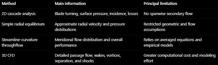
A practical design process often progresses from simplified calculations toward more detailed simulations.
Early calculations establish the approximate blade geometry, flow angles, loading, and operating conditions.
Throughflow analysis then evaluates how the flow is distributed throughout the machine and whether the design is consistent with the required performance.
Three-dimensional CFD is subsequently used to investigate local aerodynamic structures and refine the geometry.
This progression is especially useful when optimizing a turbomachine because it avoids spending expensive CFD resources on designs that are already unfavorable at the preliminary stage.
16. Engineering perspective: connecting the complete flow field
The most important connection between the different methods is the relationship between blade loading and flow redistribution.
A blade row changes the direction of the fluid by generating pressure forces. This produces a change in circumferential momentum and, for rotating blades, an exchange of energy.
The resulting swirl distribution creates radial pressure gradients, which influence the meridional velocity distribution and the geometry of the streamlines.
Boundary layers and other low-momentum regions disturb this balance, producing secondary flows, vortices, and additional losses.
At high Mach numbers, compressibility introduces shock waves and further restrictions on the operating conditions.
A useful aerodynamic design must therefore consider the interaction between these mechanisms rather than optimizing the two-dimensional blade profile in isolation.
For example, increasing the loading of a compressor blade may produce the desired flow turning in a two-dimensional cascade calculation. However, the stronger pressure gradients may also promote endwall secondary flows and corner separation in the complete three-dimensional passage.
Similarly, a favorable radial swirl distribution may produce approximately uniform work across the span but require substantial blade twist or generate unfavorable local Mach numbers.
The objective is to find a compromise between aerodynamic performance, operating range, and the practical limitations of the blade geometry.
17. Final perspective
The analysis of turbomachinery flow is built on a hierarchy of physical descriptions.
Two-dimensional cascade theory explains how blades guide the fluid, generate aerodynamic loading, and introduce losses. It establishes the importance of incidence, deviation, solidity, and compressibility in determining blade performance.
Meridional analysis extends this description across the machine span, connecting swirl, radial pressure gradients, streamline curvature, and the distribution of mass flow.
Three-dimensional flow analysis reveals the limitations of these simplified descriptions, particularly near endwalls, blade tips, and regions of strong secondary motion.
Non-reflecting boundary conditions address a different but related challenge: ensuring that the artificial boundaries of compressible CFD simulations do not introduce unwanted wave reflections.
Finally, throughflow methods such as Vista TF combine the main conservation relationships with empirical aerodynamic models to provide rapid estimates of machine performance.
The essential engineering lesson is that the required level of model complexity depends on the flow phenomena that control the design. Simplified models are extremely valuable when their assumptions remain appropriate, while detailed CFD becomes necessary when localized three-dimensional effects determine performance.