

Turbomachinery 6: Analysis and design in Turbomachines
This chapter brings the general principles of turbomachinery into the actual machines used to compress gases, extract power from hot gas streams, pump liquids and generate hydraulic power. The central engineering problem is always the same: control the exchange of angular momentum between a rotating blade row and a flowing fluid while keeping aerodynamic or hydraulic losses within acceptable limits. Axial compressors and turbines expose this problem through velocity triangles, reaction, loading and blade-row losses; radial machines add strong centrifugal effects and highly three-dimensional flow; hydraulic machines show how the same principles simplify for incompressible flow while introducing system-level effects such as head, draft-tube recovery and cavitation
1. One physical idea behind several very different machines
Axial compressors, axial turbines, centrifugal compressors, radial turbines, pumps and hydraulic turbines can look remarkably different, but they are variations of the same mechanical idea. A rotor exchanges angular momentum with a fluid. If the rotor gives energy to the fluid, the machine behaves as a compressor or pump. If the fluid gives energy to the rotor, the machine behaves as a turbine.
This is why the velocity triangle remains such a central tool throughout turbomachinery. Absolute velocity V describes the motion seen from the stationary frame, relative velocity W describes what a rotating blade experiences, and blade velocity U represents the motion of the rotor itself. They are connected by the vector relationship:
V = W + U
The circumferential component is particularly important because shaft work follows from its change across the rotor. The Euler turbomachinery relation therefore links specific work to blade speed and the change in tangential absolute velocity. In an axial compressor this change is arranged so that work is supplied to the fluid; in an axial turbine it is arranged so that work is extracted.
This immediately gives a useful way of thinking about blade design. A rotor is not simply a curved passage that accelerates or decelerates the fluid. Its purpose is to create the correct change in swirl while maintaining a flow field that the boundary layers can tolerate. Much of turbomachinery design is consequently a compromise between turning the flow enough to perform useful work and not loading the blades so strongly that separation, secondary flow, shocks or excessive losses destroy the expected performance.
The geometry determines the velocity triangles, but the actual flow never follows the geometry perfectly. Incidence appears at the leading edge, boundary layers grow along the surfaces, wakes emerge from the trailing edge, secondary flows transport low-momentum fluid through the passage, tip-clearance flow bypasses the intended blade loading, and compressibility may introduce shock waves. Consequently, one-dimensional or mean-line analysis establishes the basic design, while empirical correlations and ultimately CFD are needed to determine how closely the real machine follows that idealized picture.
2. Axial Compressors
2.1 Why axial compressors are difficult machines
An axial compressor increases pressure while keeping the dominant direction of flow approximately parallel to the machine axis. A stage normally consists of a rotor followed by a stator. The rotor supplies mechanical energy to the fluid and normally raises both its static and stagnation pressure. The stator then removes part of the kinetic energy and converts it into additional static pressure while redirecting the flow for the following rotor.
The difficulty is that compression requires diffusion. Boundary layers do not naturally like diffusion because decreasing velocity is accompanied by an adverse pressure gradient. If the pressure recovery demanded from a blade passage becomes excessive, the boundary layer thickens and can eventually separate. This places a fundamental aerodynamic restriction on how much pressure rise can reasonably be obtained from an axial stage.
This explains why an axial compressor typically uses many stages rather than trying to achieve the complete pressure ratio in one extremely highly loaded blade row. Increasing stage loading may reduce the number of stages, weight and length, but it simultaneously increases turning, diffusion and loss sensitivity.
Modern compressors therefore represent a balance between aerodynamic loading, structural constraints and compressibility. High tip speeds help increase the work available from each stage, but high relative Mach numbers introduce shock losses and stronger shock–boundary-layer interactions. The course material also connects compressor development to structural innovations such as wide-chord fan blades, which allowed aerodynamic and mechanical improvements while avoiding older mid-span supporting structures.
2.2 Mean-line analysis: reducing a 3D machine to something useful
The actual flow through a compressor is three-dimensional, viscous and highly non-uniform. Mean-line analysis deliberately ignores much of this complexity. Representative average quantities are assigned at selected stations and the stage is treated through conservation laws and velocity triangles.
That simplification is enormously useful because it exposes the parameters that actually control the machine.
For a conventional axial compressor stage:
station 1 is associated with rotor inlet,
station 2 with rotor exit,
the downstream station describes the stator exit,
U is approximately constant if the analysis follows a constant mean radius,
axial velocity is often assumed approximately constant as a first approximation.
The rotor sees relative velocity W. If the relative flow diffuses through the rotor, then typically W2 < W1. This relative deceleration contributes to a static-pressure rise. At the same time the rotor changes the circumferential component of absolute velocity, and therefore Euler work is positive: mechanical energy is supplied to the fluid.
The stator has no shaft work. Its stagnation enthalpy therefore remains essentially constant in the adiabatic treatment, while absolute velocity is reduced and part of that kinetic energy becomes static pressure.
This distinction is worth retaining:
The rotor raises total energy; both rotor and stator can contribute to static-pressure rise.
That is why looking only at static pressure in CFD can be misleading when trying to understand where compressor work enters the fluid. Total quantities and velocity triangles are required to separate work input from diffusion.
2.3 Velocity triangles are the compressor's design language
With approximately constant axial velocity, the shape of a triangle is largely determined by axial velocity, blade speed and swirl. Changing any of these changes the incidence and turning seen by the blades.
The absolute and relative frames have different engineering roles. The rotor blade must be designed around the relative flow angle because that is the velocity encountered by the rotating surface. Stationary stator blades respond to the absolute flow.
This distinction becomes especially important at off-design conditions. Suppose rotational speed remains approximately fixed but mass flow decreases. Axial velocity falls while U does not change correspondingly. The velocity triangle rotates, changing rotor incidence. The blades are now being approached at a different angle even though their geometry has obviously not changed.
That simple geometric fact is one of the roots of compressor off-design behaviour.
2.4 Degree of reaction: where does compression occur?
The degree of reaction describes how the stage static enthalpy rise is distributed between rotor and stator. In the simplified definition, it compares the rotor enthalpy rise with the total stage enthalpy rise.
A reaction around 0.5 represents a balanced arrangement in which approximately half of the stage static-pressure rise occurs in the rotor and half in the stator. This does not merely divide a thermodynamic quantity. It tells us something about the aerodynamic loading imposed on each blade row.
If too much diffusion is concentrated in one row, that row becomes more susceptible to boundary-layer growth and separation. Reaction is therefore a useful design variable because it connects the thermodynamic distribution of compression with blade aerodynamics.
2.5 Flow coefficient and loading coefficient
Two dimensionless parameters compress much of the mean-line design problem into a compact form.
The flow parameter, or flow coefficient, is approximately:
phi = axial velocity / blade speed
It describes how much flow passes through the machine relative to its rotational speed.
The load parameter, or loading coefficient, is approximately:
psi = specific work / blade speed²
It describes how much work is demanded from a stage relative to the kinetic scale established by the rotor speed.
These are not arbitrary nondimensionalizations. They define the shape of the velocity triangles.
A low flow coefficient means that U dominates the triangle. A high flow coefficient means that the through-flow velocity becomes relatively important. Increasing loading demands a larger change in tangential velocity and therefore generally stronger turning.
Reaction, flow coefficient and loading coefficient are consequently coupled. Choosing them establishes much of the basic aerodynamic architecture before an actual blade profile has been designed.
3. Why real compressor stages lose performance
3.1 Profile loss and the boundary-layer problem
A real blade surface develops a boundary layer. Viscous shear converts useful mechanical energy into internal energy and produces entropy. More importantly for compressors, the boundary layer must survive an adverse pressure gradient while the passage diffuses the flow.
At modest diffusion the layer remains attached and the compressor can recover pressure efficiently. Increasing diffusion thickens it. Beyond a certain level the near-wall fluid no longer has enough momentum to move against the pressure rise and separation develops.
This is why the aerodynamic loading of a compressor blade cannot be increased indefinitely.
The diffusion factor provides a compact engineering measure of this process. It combines deceleration and turning into a quantity correlated with blade loss and separation. It is valuable precisely because compressor failure is not controlled by velocity reduction alone: turning changes blade loading as well.
3.2 Incidence and deviation
The incidence angle measures the mismatch between incoming flow direction and blade inlet geometry. At one particular incidence the profile loss is near its minimum.
Move away from that condition and the leading-edge loading changes. Large positive or negative incidence can generate locally severe acceleration, separation and increased losses. This is one reason a compressor optimized at a design point does not retain the same efficiency everywhere on its map.
Deviation concerns the other end of the blade. The fluid leaving a passage does not generally leave exactly tangent to the trailing-edge metal angle. Boundary-layer development and the finite ability of the blades to turn the flow produce a difference between geometric and actual exit directions.
Deviation matters because the exit triangle of one blade row becomes the inlet triangle of the next. An error is therefore not necessarily local. It can propagate through a multistage machine.
3.3 Compressibility and shock losses
At sufficiently high relative Mach numbers, shock waves become another major loss mechanism. A shock produces an irreversible total-pressure loss, but its influence is broader than the shock itself. Its interaction with the blade boundary layer can produce thickening or separation, modifying the downstream flow field.
This is particularly important near the outer radius of high-speed compressor rotors, where U is greatest and relative velocities can become transonic even when the axial inlet flow is not.
The axial-compressor material therefore treats shock-wave loss models alongside profile loss, deviation, diffusion, annular boundary layers and clearance effects rather than as a completely separate topic.
3.4 Annulus boundary layers and clearance flow
The hub and casing also develop boundary layers. These interact with blade-to-blade pressure gradients and generate three-dimensional secondary-flow structures.
Rotor tip clearance introduces another mechanism. Pressure differences across the blade drive leakage through the gap. The leakage flow does not perform the same useful aerodynamic task as the core passage flow and mixes with it downstream, producing additional loss.
These effects become increasingly important when moving from mean-line calculations toward CFD. A mean-line model can represent them through correlations; a three-dimensional CFD model attempts to resolve at least their larger-scale flow structures directly.
That distinction is central to using CFD intelligently: CFD does not replace the mean-line physics. It reveals where and how the assumptions behind the mean-line model break down.
4. Axial Turbines: the same framework with reversed energy transfer
4.1 Stator–rotor cooperation
An axial turbine stage usually consists of a stator followed by a rotor. The stator acts as a nozzle. It expands the fluid, accelerating it and generating a tangential velocity component oriented so that the rotor can extract work.
The rotor then turns the flow and experiences a tangential force. Shaft power is produced because angular momentum is removed from the fluid.
In a multistage turbine, the process repeats, with each stationary row also preparing the flow for the next rotor.
Unlike a compressor, the pressure gradient associated with turbine expansion is generally favourable to the boundary layer. This gives turbines considerably more freedom to impose aerodynamic loading without immediately encountering the same diffusion limit that constrains compressors.
That does not make turbines loss-free. It simply changes which aerodynamic restrictions dominate the design.
4.2 Thermodynamic picture of an axial turbine stage
In an adiabatic stator there is no shaft work, so stagnation enthalpy is conserved. Static enthalpy falls as the fluid accelerates.
Across the rotor, shaft work is extracted. The appropriate rotating-frame quantity is rothalpy. For the simplified constant-radius treatment, conservation of rothalpy means that relative stagnation temperature remains constant through the rotor.
Meanwhile, real stators and rotors generate entropy. Total pressure therefore falls even when stagnation temperature is unchanged through a stationary adiabatic blade row.
That distinction is extremely useful when interpreting CFD:
a decrease in static pressure can simply represent intentional expansion;
a decrease in total pressure through an adiabatic stationary row identifies irreversible loss;
a change in total enthalpy across the rotor represents shaft work.
4.3 Euler work in turbine form
The turbine rotor reduces the circumferential momentum of the fluid. With the sign convention used in the material, this produces negative specific work for the fluid, meaning useful power has been extracted by the rotor.
Physically, turbine performance therefore depends heavily on how much swirl enters the rotor and how much remains when the flow leaves it.
Residual exit swirl can represent kinetic energy that has not been converted into shaft work. Designers therefore manipulate the velocity triangles so that the exit condition is appropriate for either the next stage or the final exhaust system.
5. Reaction, impulse and turbine stage architecture
Degree of reaction is just as useful for turbines as for compressors, but now it describes how the stage expansion is divided between stator and rotor.
At one conceptual extreme lies the impulse stage, where most of the pressure expansion occurs in the stator and the rotor mainly extracts momentum from the high-speed flow.
A reaction turbine allows a substantial part of the expansion to continue through the rotor itself. The relative flow therefore accelerates through the rotating passage.
The choice affects rotor and stator velocities, blade loading, loss generation and stage geometry. Reaction is thus not merely a classification label; it describes where the thermodynamic expansion occurs and therefore where the aerodynamic burden is placed.
The same dimensionless parameters used for compressors remain valuable. For turbines the flow coefficient again compares axial velocity with blade speed, while the loading coefficient compares extracted specific work with U². The material defines turbine loading with the appropriate sign so that extracted work produces a positive loading parameter.
The interaction between reaction, flow coefficient and loading determines the velocity triangles and therefore much of the stage design.
6. Loss mechanisms in axial turbines
Turbine flow remains three-dimensional, turbulent and irreversible. The principal loss families include airfoil/profile losses, secondary-flow losses and clearance-related losses, together with effects associated with trailing edges and, where relevant, compressibility.
Airfoil losses arise through boundary layers on the blade surfaces, wake formation and trailing-edge vortex shedding. Their magnitude depends on parameters including velocity level, Reynolds number, surface roughness and trailing-edge geometry.
The wake deserves particular attention. Fluid inside a blade boundary layer has lower momentum and higher entropy than the external flow. At the trailing edge the two boundary layers leave the blade and form a velocity deficit. This wake then travels toward the following blade row.
That creates the connection between apparently separate subjects:
blade boundary layer → trailing-edge wake → mixing loss → non-uniform inlet to the next row → unsteady rotor–stator interaction.
Secondary flows develop because the blade-to-blade pressure gradient acts on the low-momentum fluid contained in the endwall boundary layers. The resulting cross-passage transport concentrates loss near hub and casing regions rather than distributing it uniformly across span.
Tip leakage adds another three-dimensional structure. Pressure differences drive flow through rotor clearances, generating leakage jets and vortical structures that subsequently mix with the main flow.
A CFD calculation of a turbine stage should therefore not be judged solely by whether it reproduces an overall pressure ratio or efficiency. The physically meaningful question is whether the simulation represents the spatial organization of loss correctly: blade wakes, endwall regions, leakage structures and downstream mixing.
7. Zweifel coefficient and turbine blade loading
Turbine design needs a practical way of relating blade spacing, turning and loading. The Zweifel coefficient serves this purpose.
Its value reflects the aerodynamic loading associated with a particular cascade geometry. If blades are too widely spaced, each blade must produce greater turning force and the surface loading becomes excessive. If blades are packed too closely, the number of blades and wetted surface increase, raising friction and structural complexity.
The useful design is therefore not the configuration with the greatest possible number of blades or the smallest possible spacing. It is a compromise between loading and surface-related loss.
This is characteristic of turbomachinery design in general: there is rarely one variable that can simply be maximized. Most design parameters move one loss mechanism down while moving another one up.
8. Axial compressor versus axial turbine
The compressor and turbine chapters become easier to retain if they are treated as two versions of the same mean-line framework.
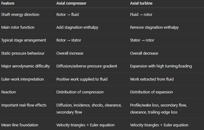
The mathematical machinery is therefore not something to learn twice. Once the relationship between U, V and W is physically understood, the distinction is largely about the desired direction of energy transfer and the resulting aerodynamic constraints.
9. Radial turbomachinery: what changes when radius changes strongly?
Axial machines operate with relatively modest radial displacement of the mean streamline. Radial machines deliberately exploit a large change in radius.
This is a profound difference because blade speed is U = Ωr. If r changes substantially through the rotor, U changes substantially as well.
That introduces a centrifugal contribution to energy transfer which is largely absent from the simplified constant-radius axial picture.
Radial machines include centrifugal compressors and pumps, radial-inflow turbines and combinations such as automotive turbochargers. Their principal advantage is the ability to achieve a comparatively large pressure change in a single stage.
10. Centrifugal Compressors
10.1 Why centrifugal compressors achieve high stage pressure ratios
A centrifugal compressor typically receives flow approximately axially into the impeller eye. The impeller turns the flow outward and discharges it radially at a much larger radius.
Because U = Ωr, the outer part of the impeller moves much faster than the inlet region.
Pressure rise inside the rotor comes from two contributions:
relative diffusion, where W decreases through the impeller passage;
centrifugal action, associated with the increase in blade speed as the fluid moves to larger radius.
This is one of the most important physical differences between axial and centrifugal compressors. An axial compressor relies heavily on aerodynamic diffusion. A centrifugal compressor can obtain a substantial part of its pressure rise from the radius change itself. Consequently it can achieve a much larger pressure ratio without requiring an equally severe amount of relative-flow diffusion.
The material gives representative centrifugal-compressor pressure ratios reaching roughly 12:1–14:1 and rotational speeds exceeding 150,000 rpm in appropriate applications. These machines are particularly attractive for low or moderate mass flows requiring substantial pressure rise. Their drawbacks include relatively large frontal area per unit mass flow and the difficulty of efficiently recovering the high velocity leaving the impeller.
10.2 Why the impeller can be efficient while the compressor is not
The impeller itself can achieve efficiencies above 90%, helped by moderate relative velocities. Yet the complete centrifugal compressor can perform substantially worse because the fluid exits the impeller with a large absolute velocity.
That kinetic energy must be recovered in the diffuser.
The diffuser therefore becomes one of the critical components of the machine. Losses increase strongly with velocity, while the large exit flow angle produces a long spiral path. High density and relatively narrow diffuser passages also create a large wetted area relative to the mass flow.
This leads to a useful engineering lesson:
Producing pressure rise inside the rotor is only part of centrifugal-compressor design. Recovering the impeller exit kinetic energy without excessive loss can be equally important.
11. The real impeller flow: jet–wake structure
A centrifugal impeller is an excellent example of why a simple mean-line solution can be correct globally while missing the dominant local physics.
The flow turns in the meridional plane, experiences centrifugal and Coriolis forces, and develops boundary layers on blades, hub and shroud. Measurements show that the flow can become strongly non-uniform near the impeller exit.
The classic jet–wake model describes this behaviour as a relatively energetic jet region occupying much of the passage alongside a low-velocity, low-total-pressure wake.
The mechanism is strongly three-dimensional. Meridional curvature drives secondary motion toward the shroud, while the blade pressure difference drives endwall boundary-layer fluid toward the suction side. High-entropy, low-momentum fluid therefore accumulates near the shroud–suction-side corner, producing the characteristic exit non-uniformity.
For CFD this is a particularly important reference pattern. A simulation producing a perfectly uniform impeller exit merely because the global pressure ratio is correct should be treated with suspicion. The real flow contains substantial spanwise and pitchwise structure.
12. Slip: why the flow does not leave exactly where the blade points
Perfect guidance would imply that the relative flow leaves exactly tangent to the impeller blade trailing edge. Real centrifugal compressors do not behave that way.
Once the fluid leaves the blade passage, the circumferential force balance imposed by the blade surfaces disappears. The flow consequently deviates opposite to the direction of rotation. This phenomenon is called slip and, importantly, its origin is not simply viscous boundary-layer deviation. The treatment emphasizes its dynamic, essentially non-viscous origin.
Slip reduces the tangential component of absolute exit velocity. Since Euler work depends directly on this component, slip reduces the actual specific work below the value predicted by perfect guidance.
The slip factor quantifies this reduction.
Blade number is one of its principal geometric influences. Increasing the number of blades generally improves guidance and reduces slip, but this again creates a design compromise because additional blades also add wetted surface, blockage and manufacturing complexity.
Correlations such as Stanitz, Busemann and related formulations provide practical estimates. The material also emphasizes their limitation: purely geometric or theoretical correlations do not fully represent the jet–wake structure of a real centrifugal impeller
13. Impeller exit angle and backsweep
The blade exit angle controls the impeller velocity triangle and therefore influences work input, pressure rise and operating behaviour.
Changing the amount of backsweep changes the tangential component of exit velocity. A geometry producing greater tangential velocity tends to increase Euler work, but that does not automatically mean it gives the best complete compressor.
The exit angle also changes diffuser inlet conditions, slip behaviour and the sensitivity of work to mass flow. The impeller therefore cannot be optimized independently of the downstream diffuser.
This is another recurring turbomachinery theme: a blade row should be designed for the component that follows it, not merely for its own isolated efficiency.
14. Radial-inflow turbines
A radial turbine essentially uses the radial geometry in the opposite energy direction. The flow enters at relatively large radius and moves inward through the rotor while mechanical energy is extracted.
Radial turbines are particularly common in turbochargers and other relatively small machines. Their geometry permits substantial work extraction in a compact stage, while moderate rotor inertia can provide the fast transient response desirable in applications such as engine boosting.
As with axial turbines, velocity triangles and the Euler relation establish the work. But the substantial change in radius means that the changing U cannot be neglected.
The radial machine is therefore not simply an axial stage bent by 90 degrees. Centrifugal effects, meridional curvature and three-dimensional secondary flow are fundamental parts of its operation.
15. Vaned and vaneless diffusion
After a centrifugal impeller, the high-speed flow must be slowed to recover static pressure.
A vaneless diffuser performs this through radial expansion without blade passages. As radius increases, conservation of mass and angular momentum alters the radial and tangential velocity components, producing a spiral trajectory while kinetic energy is converted into static pressure.
The attraction is geometric simplicity and comparatively broad operating behaviour. The difficulty is that the flow travels over substantial wetted surface and the path becomes particularly long when the tangential component is large. Friction therefore matters strongly.
The course treatment develops both an ideal isentropic solution and a total-pressure-loss description, making the distinction between ideal pressure recovery caused by changing velocity and irreversible loss caused by wall friction.
This distinction should also guide CFD post-processing. Static-pressure recovery alone does not prove that a diffuser is good. Total-pressure loss must be examined at the same time.
16. The volute: collecting radial flow without destroying what the impeller achieved
A centrifugal compressor eventually needs to transform the annular/radial discharge into a conventional duct. The volute performs this task.
Its cross-sectional area increases around the circumference because progressively more mass flow has entered the volute as the azimuthal angle increases. Ideally, its geometry accommodates this increasing flow while maintaining appropriate velocity and pressure behaviour.
The volute can participate in pressure recovery, but it also introduces an unavoidable loss of axisymmetry. The tongue region is especially important because it closes the spiral collector and interacts with the incoming diffuser flow. Poor sizing can produce mixing losses and circumferential non-uniformity large enough to significantly degrade overall machine performance.
A simplified sizing approach therefore relates local volute area to accumulated mass flow and uses angular-momentum considerations for the tangential velocity. The course also identifies logarithmic-spiral geometry as a natural possible construction, although other geometries can be used
17. Hydraulic machines: turbomachinery with an incompressible fluid
Water turbines and pumps obey the same conservation laws as gas turbomachinery, but incompressibility simplifies the thermodynamic side considerably.
Density changes no longer dominate the analysis. Machine performance can therefore be expressed particularly cleanly through flow and loading parameters. For a pump operating away from significant cavitation and sufficiently high Reynolds number, the load coefficient and efficiency can be regarded primarily as functions of flow coefficient and geometry.
The typical pump characteristic contains an efficiency maximum at a particular flow coefficient. That operating point is naturally important for design.
A simplified one-dimensional model can produce an approximately linear relation between loading and flow coefficient, but the actual curve departs from that ideal because the real machine contains deviation, viscous effects, separation and other nonlinear behaviour
18. Hydraulic head and the complete installation
Hydraulic turbomachinery cannot be understood by examining the runner alone. The available energy is set by the hydraulic installation.
Bernoulli's relation combines elevation, pressure and kinetic energy into a hydraulic-energy description. In an ideal line without losses these contributions exchange with one another while their total remains constant. Friction decreases the available hydraulic energy, a pump adds it, and a turbine removes it as shaft work.
This is why civil geometry is an integral part of hydro-turbine design. Reservoir elevation, penstocks, turbine location and downstream channel conditions all affect how much energy can actually reach the runner.
The draft tube provides a particularly clear example.
A turbine may discharge with substantial velocity. If that kinetic energy is simply dumped into a large downstream reservoir, it is degraded through mixing. A properly designed expanding draft tube slows the flow and recovers pressure, allowing more of the available hydraulic head to be exploited by the turbine.
So even though the draft tube does not extract shaft work itself, it can strongly affect the useful power of the complete installation.
19. Choosing between Kaplan, Francis and Pelton turbines
Hydraulic turbine type is strongly related to available head and flow rate.
Kaplan
Kaplan turbines are axial-flow reaction machines suited to relatively low heads and large flows. Their geometry resembles a propeller, but the runner blades can change pitch.
The guide vanes regulate the incoming flow. When operating conditions change, the corresponding velocity triangle changes as well. Adjusting runner-blade angle helps maintain suitable incidence and therefore avoids excessive incidence loss. A fully adjustable arrangement is referred to as a true Kaplan turbine.
This makes Kaplan turbines particularly well adapted to installations where flow changes significantly.
Francis
Francis turbines are reaction machines in which the flow typically enters the runner radially and leaves approximately axially. A volute distributes water around the machine, guide vanes establish the required inlet direction, and the runner performs the work extraction.
They occupy a broad intermediate region of hydraulic-turbine application and are widely used where both head and flow are moderate.
Pelton
The Pelton turbine is fundamentally different. It is an impulse turbine.
The available hydraulic head is first converted into a high-speed free jet by a nozzle. That jet strikes buckets around the rotor circumference. Each bucket divides and redirects the jet through a large angle, producing torque through momentum change.
Pelton turbines are therefore suited to very high head and relatively low flow.
The basic application trend is:
low head / high flow → Kaplan
intermediate conditions → Francis
high head / low flow → Pelton
The material also notes crossflow and Turgo designs as alternatives in parts of the hydraulic operating envelope
20. Specific speed: connecting operating conditions to machine geometry
Specific speed is valuable because it connects machine speed, flow and energy transfer into a parameter associated with the type of turbomachine that best suits an application.
For hydraulic turbines, different machine families occupy different specific-speed regions. Pelton turbines belong toward the low-specific-speed end, Francis turbines occupy intermediate conditions, and Kaplan turbines operate at high specific speed.
This is not merely an empirical classification. It reflects geometry.
A machine intended to process a large flow with comparatively small specific energy must have a fundamentally different passage arrangement from one processing a small flow under enormous head.
Specific speed therefore provides an early design decision before detailed blade geometry is considered.
The same idea appears in centrifugal turbomachinery. Experimental impeller data show an efficiency optimum around a characteristic range of specific speed, demonstrating again that a machine cannot be scaled arbitrarily while retaining ideal aerodynamic proportions.
21. Cavitation: when incompressibility stops being enough
Hydraulic analysis often treats water as a single incompressible liquid, but this assumption becomes inadequate when local pressure falls sufficiently.
If pressure approaches the liquid vapour pressure, vapour cavities can form. Their subsequent collapse can generate intense local loads, erosion, vibration and performance degradation.
The critical point is that cavitation depends on local minimum pressure, not simply the average inlet or outlet pressure.
A pump is particularly vulnerable near its inlet because this is commonly where the lowest pressure occurs. Turbines, by contrast, can encounter their critical low-pressure region near the runner discharge and draft tube. Cavitating vortices may develop within the draft tube, while collapse near blade surfaces can cause erosion.
The pressure coefficient provides a dimensionless description of the internal pressure field. Once machine geometry and operating flow coefficient are specified, this provides a way of relating the minimum internal pressure to inlet conditions.
21.1 NPSH and cavitation margin
For pumps, net positive suction pressure — NPSP/NPSH in the formulations used in the addendum — expresses how much inlet total-pressure margin remains above vapour pressure.
Conceptually, this is the quantity to remember:
The pump must arrive at its inlet with enough pressure margin that the additional local pressure depression created by acceleration and blade loading does not drive the liquid into cavitation.
The characteristic suction speed provides another nondimensional way of describing suction performance. The Thoma cavitation parameter similarly relates available pressure margin to the energy scale of the machine.
These parameters are useful because merely stating an absolute inlet pressure says little without knowing speed, geometry, flow and vapour pressure.
The material also makes an important qualification: cavitation inception is more complicated than simply checking p < vapour pressure. Nucleation conditions and the fluid state affect the onset of observable cavitation. Consequently, experimental cavitation limits remain important.
22. Overspeed in hydraulic turbines
Hydraulic turbines normally drive synchronous electrical generators, so their operating rotational speed is closely tied to electrical frequency.
A dangerous condition appears if generator load is suddenly removed. The turbine can temporarily remain exposed to hydraulic torque without the balancing generator torque, causing rapid acceleration.
The material gives runaway/overspeed values of roughly 1.8–2.2 times design speed as representative values that must be considered structurally.
This is an excellent example of why turbomachinery cannot be designed purely from steady-state CFD at the nominal operating point. The aerodynamic or hydraulic design, mechanical integrity and system transient behaviour are connected.
23. From mean-line theory to CFD
The one-dimensional theory throughout these chapters should not be viewed as an obsolete approximation that CFD replaces. It serves a different purpose.
Mean-line analysis establishes:
the expected velocity triangles,
work transfer,
reaction,
flow and loading coefficients,
pressure and temperature evolution,
expected incidence and deviation,
the approximate distribution of aerodynamic loading.
CFD then exposes the mechanisms hidden inside those averaged quantities.
For an axial compressor, useful CFD diagnostics include relative Mach number in the rotor, static and total-pressure distributions, blade-surface pressure, incidence, diffusion, boundary-layer development, wakes, tip leakage and secondary flows.
For an axial turbine, the focus shifts toward expansion, acceleration, blade loading, entropy generation, wakes, endwall secondary flow and clearance loss.
For a centrifugal compressor, the flow demands genuinely three-dimensional analysis. The shroud–suction-side low-momentum region, jet–wake structure, impeller slip, diffuser recovery and volute circumferential non-uniformity are especially important.
For hydraulic machines, pressure deserves particular attention because the absolute local pressure determines cavitation risk. A CFD solution that predicts head and efficiency correctly but misses the minimum pressure near the blade can still fail to predict an essential design limitation.
24. A useful hierarchy for interpreting turbomachinery CFD
When looking at a new Fluent result, there is a natural sequence that prevents getting lost in attractive contour plots.
First establish mass conservation and operating point. The machine must be processing the intended mass or volume flow at the intended rotational speed.
Then establish energy transfer. Compare stagnation quantities and torque with the direction and magnitude expected from Euler's equation.
Next examine velocity triangles and flow angles. Confirm that the rotor sees approximately the intended incidence and that the actual exit flow direction is reasonable.
Only then investigate loss generation: total-pressure loss, entropy, wakes, separation, secondary flows, clearance structures and shocks.
Finally examine the downstream consequences. A rotor wake enters another blade row; an impeller exit profile enters a diffuser; residual swirl enters an exhaust or draft tube; a non-uniform diffuser exit enters a volute.
This is more informative than asking whether a contour simply "looks reasonable."
25. What TO remember from this chapter
The five documents contain many correlations and detailed design relations, but a much smaller set of ideas forms the long-term framework.
Euler work is the backbone. A turbomachine exchanges shaft work by changing the fluid's angular momentum. Tangential velocity matters because torque comes from swirl.
Velocity triangles connect geometry to energy transfer. Absolute velocity describes the stationary machine, relative velocity describes what the rotor blade experiences, and blade velocity connects the two.
Compressors are fundamentally limited by diffusion. Pressure recovery creates adverse pressure gradients, which make boundary-layer separation one of the defining aerodynamic constraints of compressor design.
Turbines tolerate greater aerodynamic loading because expansion produces more favourable pressure-gradient behaviour, although profile loss, secondary flow, wakes, clearances and unsteadiness still determine efficiency.
Reaction tells where the pressure/enthalpy change occurs. It is therefore a measure of how aerodynamic loading is distributed between stationary and rotating rows.
Flow coefficient tells how fast the fluid passes through relative to the blade; loading coefficient tells how much work is demanded relative to blade speed. Together with reaction they largely determine the velocity triangles.
Radial compressors gain an additional mechanism: centrifugal pressure rise. That is why they can achieve high pressure ratios per stage without demanding all of the pressure rise from aerodynamic diffusion.
The centrifugal impeller exit is strongly three-dimensional. Secondary flow drives high-entropy fluid toward the shroud–suction-side region and produces the jet–wake structure.
Slip means the impeller does not perfectly guide the exit flow. It reduces tangential velocity and therefore actual Euler work.
The diffuser and volute matter as much as the impeller to complete-machine performance. Producing high kinetic energy efficiently is of little use if that energy is subsequently destroyed during pressure recovery or collection.
Hydraulic machines obey the same turbomachinery physics but incompressibility simplifies the thermodynamics. Their operation becomes naturally described in terms of head, flow coefficient, loading and specific speed.
Kaplan, Francis and Pelton are different solutions to different combinations of head and flow, rather than competing versions of the same geometry.
Cavitation is controlled by the lowest local pressure. NPSH and related cavitation parameters express the pressure margin between normal liquid operation and vapour formation.
And finally:
Mean-line theory tells you what the machine should do; CFD tells you how the real three-dimensional flow prevents it from doing that perfectly.