

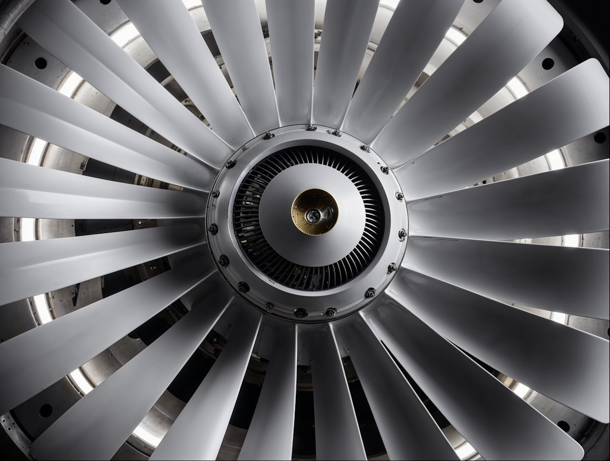
This chapter establishes the fundamental framework for understanding turbomachinery and its numerical simulation. It introduces the classification and architecture of turbines, compressors, and pumps, focusing on how rotating and stationary blade rows exchange energy with the fluid. The chapter then examines the complex flow physics encountered inside turbomachines, including boundary layers, wakes, secondary flows, tip-clearance effects, separation, compressibility, shock waves, and turbulence. Finally, it introduces the role and limitations of CFD in turbomachinery design and outlines the ANSYS workflow from preliminary meanline design and blade geometry generation to meshing, flow simulation, and iterative design improvement.
1. What this chapter is really about
Turbomachinery starts with a fairly simple idea: transfer energy between a rotating mechanical system and a flowing fluid. Depending on the direction of that transfer, the machine can either extract useful mechanical power from the fluid or supply mechanical energy to it.
The difficulty begins when we look at how that exchange actually happens.
The fluid has to pass through rotating and stationary blade rows while dealing with pressure gradients, viscosity, turbulence, three-dimensional effects and, in many machines, compressibility. Rotors move relative to stators, blade boundary layers develop into wakes, small gaps generate leakage flows, and neighbouring blade rows continuously influence one another.
This is where CFD becomes particularly useful. It gives us access to the internal flow field and allows us to investigate phenomena that would otherwise be difficult to observe. At the same time, turbomachinery CFD requires considerable simplification and modelling, so a numerical result should never be treated as automatically correct simply because the solver converged.
The complete design process therefore connects several levels of analysis:
performance requirements → preliminary design → blade geometry → CAD → mesh → CFD → performance assessment → design iteration
That sequence is a useful framework for almost everything that follows.
2. What exactly is a turbomachine?
A turbomachine is a machine that continuously exchanges energy with a flowing fluid through the action of rotating and stationary components.
The word continuously is important. A turbomachine does not trap a fixed amount of fluid, compress or expand it, and then discharge it in repeated cycles in the way a positive-displacement machine does. Instead, fluid continuously enters, interacts with the machine and leaves.
The direction of the energy transfer gives us the first major distinction.
Turbines
A turbine extracts energy from the fluid.
The incoming fluid contains energy in the form of pressure, temperature and motion. Its interaction with the turbine blades produces torque on the rotor, which can then be used as mechanical shaft power.
This is the basic principle behind gas turbines, hydraulic turbines and many other power-producing machines.
Compressors and pumps
Compressors and pumps work in the opposite direction. The shaft drives the rotor, and the rotor transfers mechanical energy into the fluid.
The result is generally an increase in fluid pressure and energy.
The terminology usually follows the working fluid: compressors are associated mainly with gases, where compressibility can become important, while pumps are normally associated with liquids, which can often be treated as approximately incompressible.
So despite the enormous variety of turbomachinery, the basic question is always the same:
Which way is the energy going?
3. The major ways turbomachines are classified
There is no single classification that completely describes a turbomachine. The same machine can be classified according to its energy transfer, flow direction, working fluid, geometry and the way pressure changes through its components.
These classifications are useful because they already tell us something about the expected flow physics.
3.1 By direction of energy transfer
The most fundamental distinction is between machines that extract energy and machines that add energy.
Machine | Energy transfer
Turbine | Fluid → shaft
Compressor | Shaft → gas
Pump | Shaft → liquid
A turbine is therefore fundamentally a power-producing machine, while a compressor or pump requires external shaft power.
That difference will eventually determine the sign and interpretation of the work transfer when turbomachinery energy equations are introduced.
3.2 By direction of flow
Another important classification describes the main fluid path relative to the rotation axis.
In an axial machine, the flow travels predominantly parallel to the shaft. Axial compressors and turbines are particularly common in aircraft engines and large gas turbines because many stages can be arranged sequentially along the same axis.
In a radial machine, the fluid experiences a large change in radius. A centrifugal compressor is a typical example: the fluid enters roughly along the rotation axis and is redirected outward through the rotating impeller.
A mixed-flow machine sits somewhere between these two arrangements, combining axial and radial components of motion.
This distinction is much more than a convenient description of geometry. Flow direction influences blade shape, centrifugal effects, machine dimensions, achievable pressure changes and the three-dimensional structures that develop inside the passages. It also affects how the CFD domain itself needs to be constructed.
4. Open versus ducted turbomachinery
Turbomachines can also be separated according to whether the fluid is confined by surrounding walls.
In a ducted machine, the fluid moves through passages bounded by components such as the hub, casing and blades. Compressors, pumps and gas turbines fall into this category.
An open turbomachine interacts with a fluid that is not enclosed in the same way. Propellers and wind turbines are familiar examples.
This difference has a major effect on the surrounding flow. A ducted compressor has to deal with wall boundary layers, confined blade passages and small clearances between rotating and stationary components. A wind turbine interacts instead with a large external flow and develops a wake that can extend far downstream.
The same underlying principle of rotor–fluid energy exchange applies to both, but the aerodynamic problems can look very different.
For most of this course, the main focus is on continuous-flow, ducted axial and radial compressors and turbines, particularly machines associated with aero engines and gas turbines.
5. Impulse versus reaction machines
Turbomachines can also be classified according to where the pressure change takes place.
In an impulse machine, most of the pressure change occurs in the stationary components. These stationary passages accelerate and direct the flow before it interacts with the rotor. The rotor then extracts energy primarily from the resulting high-velocity flow.
In a reaction machine, significant pressure changes occur in both the stationary and rotating blade rows. The rotor therefore participates directly in the pressure change as well as exchanging momentum with the flow.
This distinction becomes particularly useful when analysing turbine stages because it tells us how the aerodynamic loading and expansion are distributed between stator and rotor.
At this stage, the useful idea is simply:
impulse and reaction describe how the work of changing the fluid state is shared between stationary and rotating components.
6. Rotor, stator and stage: the basic architecture
Three terms appear constantly in turbomachinery: rotor, stator and stage.
The rotor is the rotating part of the machine. It is directly connected to the shaft and is therefore where mechanical energy passes between the fluid and the rotating system.
The stator is stationary. Its purpose is not simply to hold the machine together; its blades actively control the flow direction and pressure distribution so that the fluid reaches the rotor, or the following stage, under suitable conditions.
A stage combines a rotor and a stator into a functional aerodynamic unit. Multistage machines repeat these blade rows along the flow path, allowing the total required energy transfer to be distributed over several smaller steps.
Both rotor and stator blades have airfoil-like sections because their purpose is fundamentally aerodynamic. Pressure differences develop across the blade surfaces, producing forces that turn, accelerate or decelerate the fluid.
The important point is that rotor and stator should not be considered independently. Each blade row prepares the flow for whatever comes next.
7. Compressor versus turbine architecture
Compressor and turbine blades perform related aerodynamic tasks, but their geometry can look noticeably different because they operate under different loading and thermal conditions.
Compressor blades
Axial compressor blades are generally relatively thin and can be strongly twisted from hub to tip.
The twist is necessary because conditions are not constant along the blade span. The outer part of a rotating blade travels much faster than the section near the hub, so the local flow seen by the blade changes with radius. A single unchanged profile orientation would therefore not work equally well everywhere.
The annular flow path can also change area as the fluid progresses through the compressor. As pressure and density increase, the geometry must adapt to maintain the required flow conditions.
This is an early indication of why a real compressor cannot be fully understood from a single two-dimensional blade section.
Turbine blades
Turbine blades often have greater curvature and thickness because they can operate under high aerodynamic loading while also facing severe structural and thermal requirements.
Temperature is particularly important in gas turbines. The gas entering the turbine can be hot enough that the blade material requires active cooling to survive.
One common solution is film cooling. Cooler air is supplied through internal passages and discharged through small holes in the blade surface. This air forms a protective layer between the blade and the hotter main gas stream.
A turbine blade therefore becomes much more than an aerodynamic profile. Its design has to balance:
aerodynamics, heat transfer, cooling, materials and structural strength.
Improving one of these aspects can easily make another more difficult.
8. Why turbomachinery became technologically important
Modern turbomachinery has developed enormously in terms of the amount of energy that can be transferred through a relatively compact machine.
Aero engines provide a particularly clear example. Over decades of development, compressor pressure ratios have increased from only a few-to-one to several tens-to-one, turbine inlet temperatures have risen dramatically, and the largest machines now handle mass flows orders of magnitude greater than early engines.
These improvements did not come from aerodynamic design alone.
Higher turbine temperatures required better high-temperature materials and increasingly sophisticated cooling. Higher compressor pressure ratios required better control of blade aerodynamics, losses and stability. Increasing rotational speeds placed greater demands on structural design and manufacturing accuracy.
Modern turbomachinery is therefore inherently multidisciplinary.
Its performance depends on progress in:
aerodynamics,
materials,
cooling and heat transfer,
structural mechanics,
manufacturing.
That is also why simulation has become so valuable. Many important design decisions can no longer be made by considering one physical discipline in isolation.
9. Gas-turbine applications
Gas turbines appear in a surprisingly broad range of applications, and their architecture changes considerably with size and purpose.
Heavy-duty gas turbines are designed primarily for large-scale electricity generation. They use robust construction and predominantly axial compressor and turbine stages. Power outputs can range from a few megawatts to several hundred megawatts, with efficiencies roughly in the 30–45% range.
Aeroderivative gas turbines originate from aircraft-engine technology. They are generally lighter and more compact and can be used for applications ranging from power generation to pumping and marine propulsion. Their efficiency can be comparable with large heavy-duty machines despite the different design priorities.
Industrial gas turbines occupy a somewhat smaller power range and are frequently used for mechanical-drive applications such as petroleum pumping. Their efficiency can be improved by recovering heat or integrating them into combined-cycle systems.
Small gas turbines often rely more heavily on radial components such as centrifugal compressors and radial turbines. Their efficiency is generally lower, but their simpler construction and lower cost can be more important than achieving the highest possible aerodynamic performance.
At still smaller scales, microturbines can provide tens or hundreds of kilowatts for distributed, isolated or auxiliary power generation.
The interesting part is not the exact power range of each category. It is the way the design changes with the application.
A configuration that makes sense for a large power station may be completely inappropriate for a compact auxiliary power unit. Scale, efficiency, manufacturing cost, weight and operating requirements all influence the architecture.
10. Hydraulic turbomachinery
The same principles also apply when the working fluid is a liquid.
Three classical hydraulic turbines illustrate how different architectures can extract energy from flowing water.
A Pelton turbine uses one or more high-speed water jets directed onto buckets around the rotor. Only part of the rotor interacts with the incoming flow at any instant, making it a partial-admission machine.
A Francis turbine uses a radial component of flow as water enters the rotor and is guided through the machine by surrounding stationary components.
A Kaplan turbine is predominantly axial and resembles a large propeller operating inside a water passage.
These three machines perform the same broad task — converting hydraulic energy into shaft power — but use very different flow arrangements to do it.
That makes hydraulic turbines a useful reminder that there is rarely one universally best turbomachinery configuration. The most suitable architecture depends on the available pressure, flow rate, rotational speed and operating environment.
11. Extreme applications: rocket turbopumps
Rocket engines provide one of the more extreme turbomachinery applications.
Liquid-fuelled engines need to deliver enormous quantities of fuel and oxidizer into a combustion chamber operating at very high pressure. Simply storing the propellants at the required injection pressure would create impractically heavy tanks, so powerful turbopumps are used instead.
Separate pumps can handle the fuel and oxidizer, with centrifugal stages raising their pressure before they enter the combustion chamber. Turbines provide the shaft power required to drive these pumps.
Pressures can exceed hundreds of bar, while the complete system still needs to remain compact and lightweight.
The operating environment introduces several additional problems. Cryogenic liquids can create difficult material and sealing conditions. Pumps may have to operate close to cavitation limits, while turbine stages can experience extremely high velocities and even supersonic flow.
Rocket turbopumps therefore push several turbomachinery problems toward their limits simultaneously:
very high power density,
high rotational speed,
severe pressure requirements,
low system weight,
cavitation risk,
compressible high-speed turbine flow.
They are a good demonstration of how the basic rotor–fluid energy exchange remains the same even when the engineering environment becomes extreme.
12. Why CFD is especially important in turbomachinery
The interior of a turbomachine is a difficult place to investigate experimentally.
The geometry is compact, blades may rotate at very high speed, passages are narrow, and many important flow structures are three-dimensional and unsteady. Measurements remain essential, but obtaining detailed information everywhere inside the machine can be difficult and expensive.
CFD provides something complementary: access to the complete predicted flow field.
Instead of knowing pressure or velocity only at a limited number of measurement locations, we can investigate how these quantities vary throughout the blade passage. We can examine boundary layers, wakes, separation, leakage flows, shocks and secondary-flow structures, and then relate them to the overall machine performance.
CFD is also useful before hardware exists.
Different blade shapes, operating points and geometric modifications can be tested numerically, allowing poor ideas to be discarded before committing to expensive manufacturing and experimental campaigns.
This does not make experiments obsolete. CFD depends on physical models, numerical approximations and boundary conditions, all of which introduce uncertainty.
The two approaches are strongest when used together:
experiments establish reality; CFD helps explain it and explore alternatives.
13. Why turbomachinery CFD is difficult
The flow inside a turbomachine combines several difficult characteristics at once. It is generally three-dimensional, turbulent, compressible and unsteady.
Each of those words matters.
Three-dimensional flow
The fluid does not simply travel neatly from the leading edge to the trailing edge between two blades.
Pressure gradients exist across the blade passage and along the span between hub and casing. Boundary layers develop on several intersecting surfaces, and rotation introduces additional effects. As a result, velocity components develop in directions that would not appear in a simple two-dimensional representation.
These secondary motions can become an important source of aerodynamic loss.
Unsteady flow
A rotor continuously moves relative to the stationary parts around it.
A rotor blade therefore does not encounter exactly the same incoming flow at every instant. It passes through wakes and disturbances created by upstream stationary blades, while its own flow structures travel downstream and interact with subsequent components.
The real machine is therefore inherently unsteady.
Simulating all of this motion directly is possible, but expensive. A common engineering simplification is to analyse the rotor in a rotating reference frame, where the blade appears stationary and the flow is treated as steady.
This greatly reduces computational cost, but it comes with a price: genuinely time-dependent rotor–stator interactions are no longer resolved.
This is a recurring theme in turbomachinery CFD. We simplify the real physics to make the problem computationally manageable, and then need to understand what information was lost through that simplification.
14. How blades actually exchange energy with the flow
A turbomachinery blade resembles an airfoil, with a rounded leading edge, a pressure surface, a suction surface and a relatively sharp trailing edge.
The names pressure side and suction side already hint at the basic mechanism.
Different pressures develop on the two sides of the blade. That pressure difference produces an aerodynamic force.
For a stationary blade row, that force primarily redirects and conditions the flow. For a rotating blade row, the situation becomes more interesting because the blade itself is moving. The aerodynamic force can therefore transfer mechanical energy between the fluid and the shaft.
In a compressor, the rotor does work on the fluid.
In a turbine, the fluid does work on the rotor.
This gives a useful physical interpretation before introducing any formal turbomachinery equations:
blade loading creates aerodynamic force, and the interaction of that force with a moving rotor produces energy transfer.
Much of the mathematics introduced later simply gives us a more precise way of describing this physical process.
15. Boundary layers and wakes
Real fluids are viscous, so the fluid touching a solid blade surface cannot simply slide freely past it.
A boundary layer develops along the blade. Velocity changes rapidly from the stationary blade surface to the faster-moving external flow, creating strong velocity gradients and viscous losses.
The boundary layer becomes thicker as it travels downstream.
When the boundary layers from the pressure and suction surfaces leave the trailing edge, they contribute to a wake behind the blade. The wake contains fluid with lower momentum than the surrounding flow and represents a region where part of the useful mechanical energy has been degraded by viscous effects.
In a multistage machine, that wake does not simply disappear.
It travels downstream and becomes part of the inlet condition seen by the next blade row. A rotor or stator may therefore encounter periodically varying velocity and pressure because it is repeatedly passing through wakes generated upstream.
So even this apparently simple sequence creates several connected effects:
viscosity creates boundary layers, boundary layers contribute to wakes, wakes introduce losses and non-uniformity, and those non-uniformities affect downstream blade rows.
16. Secondary flows
If the flow through a blade passage were perfectly two-dimensional, most of the fluid would simply follow the passage from inlet to outlet.
Real turbomachinery is not that cooperative.
The blade pressure field interacts with the boundary layers developing on the hub, casing and blade surfaces. Fluid with relatively low momentum near these walls responds differently to the pressure gradients than the faster-moving fluid farther away.
The result is motion across the passage in addition to the desired main flow. These three-dimensional motions are collectively described as secondary flows.
They can produce several recognizable structures:
passage vortices,
corner flows,
endwall flow structures,
horseshoe-type vortices around blade/endwall junctions,
interactions with blade wakes,
interactions with tip-clearance flow.
These structures redistribute momentum through the passage and generally introduce additional aerodynamic loss. They are especially important near the hub and casing, which means that conditions near the endwalls can be quite different from those around the middle of the blade span.
This is why a clean two-dimensional blade profile can only tell part of the story.
A real blade passage is better thought of as a three-dimensional aerodynamic system, where blade loading, wall boundary layers, pressure gradients, wakes and vortical structures all interact with one another.
And from here, the next problem follows naturally: at the outer end of a rotor blade, the unavoidable gap between the blade tip and casing introduces yet another three-dimensional flow mechanism — tip-clearance flow.
17. Tip-clearance flow
A rotating blade cannot touch the stationary casing around it. A small gap therefore has to remain between the blade tip and the casing, and although this clearance may be small compared with the blade height, its aerodynamic influence can be significant.
The two sides of a loaded blade are at different pressures. Near the tip, this pressure difference drives fluid through the clearance from the pressure side toward the suction side. Instead of remaining aligned with the main flow, this leakage rolls up into a strong three-dimensional structure known as the tip-leakage vortex.
This affects the machine in several ways:
part of the flow bypasses the intended blade passage,
additional mixing and aerodynamic losses are introduced,
the flow near the casing becomes highly three-dimensional,
the effective loading near the blade tip changes.
In compressors, tip-clearance flow becomes particularly important when operating close to the stability limit. The interaction between the leakage vortex, casing boundary layer, and incoming flow can contribute to the development of rotating stall, where parts of the compressor annulus experience severely disturbed or separated flow.
This makes the tip clearance a good example of a recurring turbomachinery problem: a geometrically tiny feature can have a noticeable effect on the performance and stability of the whole machine.
18. Compressibility and shock waves
As blade speed increases, compressibility becomes increasingly important. This is especially relevant in modern high-speed compressors, where the relative velocity seen by the rotating blades can become transonic even when the machine as a whole does not appear to be operating at an exceptionally high flight speed.
Once parts of the flow become locally supersonic, shock waves can form inside the blade passages.
A shock produces a very rapid change in the flow properties. The velocity decreases while pressure, temperature and density change over a very short distance. More importantly from a turbomachinery perspective, this process introduces aerodynamic losses.
Shock waves can also interact with the boundary layer developing on the blade surface. If that interaction is sufficiently strong, the boundary layer may thicken considerably or even separate.
This creates a difficult design compromise. High rotational speed allows a compact machine to transfer large amounts of energy, but it also strengthens compressibility effects and may introduce additional losses that would not exist at lower Mach numbers.
For CFD, the position and strength of shocks therefore become useful indicators of whether a transonic blade design is behaving as intended.
19. Turbulence and modeling uncertainty
Turbomachinery flows are normally turbulent, but turbulence does not exist independently from everything else happening inside the machine.
The turbulent boundary layer has to deal with blade curvature, strong pressure gradients, rotation, wakes from upstream blades, secondary flows and, in high-speed machines, shock waves. Near the hub, casing and blade tip, several of these effects can occur simultaneously.
Resolving every turbulent scale directly would require far more computational effort than is practical for most engineering simulations. Instead, part of the turbulent motion has to be represented by a turbulence model.
This introduces an unavoidable source of uncertainty.
A CFD solution may converge perfectly from a numerical point of view while still giving an imperfect description of the actual flow because the turbulence model cannot reproduce every physical mechanism equally well.
That distinction is important:
numerical convergence does not automatically mean physical accuracy.
A convincing turbomachinery simulation therefore needs more than low residuals. The predicted flow structures, losses and overall machine behaviour also need to make physical sense.
20. How accurate is CFD?
This becomes particularly interesting in turbomachinery because the improvements engineers are searching for can be very small.
An industrial CFD prediction may contain uncertainties of around a few percent once the effects of numerical discretization, physical models and boundary conditions are considered. At the same time, an aerodynamic designer may be interested in an efficiency improvement of only around half a percentage point.
At first this sounds like a serious problem. How can a simulation with larger absolute uncertainty be useful for finding such a small improvement?
The answer lies in how CFD is used.
Rather than treating every calculated number as an exact prediction of reality, CFD is often much more useful for comparing closely related designs.
21. Comparative CFD: where simulation becomes especially useful
Suppose we simulate a baseline blade and then make a relatively small geometry modification.
If both cases use the same:
mesh strategy and comparable resolution,
turbulence model,
numerical schemes,
convergence criteria,
boundary conditions,
post-processing methods,
then many of the uncertainties are shared between the two simulations.
The absolute efficiency predicted for either design may not be perfect, but the change between the two cases can still contain useful engineering information.
Did the modification reduce separation?
Did the wake become weaker?
Did the tip-leakage structure improve or deteriorate?
Did the pressure rise increase without introducing excessive losses elsewhere?
This is one of the strongest uses of CFD in turbomachinery design. It allows engineers to investigate why one design behaves differently from another rather than relying only on a single performance number.
Experimental data makes this approach even stronger. Once a numerical model has been compared against measurements for a known configuration, nearby operating points or relatively small design modifications can be investigated with greater confidence.
22. What designers actually look for in CFD
Looking at colourful pressure and velocity contours is not the objective by itself. The useful part is identifying flow behaviour that explains the performance of the machine.
Several recurring features deserve particular attention.
Incidence
Incidence describes how the incoming flow direction relates to the orientation of the blade leading edge.
A blade is designed to receive the flow within a certain range of angles. If the incoming flow approaches at an unsuitable angle, the flow around the leading edge becomes less favourable and losses can increase significantly.
In compressors, incidence is closely connected to the usable operating range. As the operating condition changes, the flow angle entering the blades changes as well. Eventually this can contribute to separation and compressor instability on one side of the operating range, while choking limits the other.
Incidence also varies along the blade span. Conditions near the hub and casing can differ considerably from those around mid-span because of boundary layers and secondary flows.
So a blade cannot really be judged by a single incidence value.
Friction losses
Every wetted surface introduces viscous effects.
Boundary layers grow along the blades, hub and casing, consuming useful mechanical energy and contributing to the wakes leaving each blade row.
There is therefore an obvious temptation to reduce surface area as much as possible, but turbomachinery design rarely allows such simple optimization. Changing the number of blades, for example, also changes blade loading, passage geometry and flow guidance.
Reducing one loss mechanism can easily strengthen another.
This is one reason turbomachinery design is usually a compromise rather than a search for one independently optimized parameter.
Separated flow
A boundary layer can remain attached only while it has enough momentum to continue moving against the pressure conditions imposed by the surrounding flow.
Strong deceleration can cause the boundary layer to thicken and eventually detach from the surface.
Once separation develops, the effective flow passage changes and losses increase. Large separated regions can also generate unsteady vortical structures, affecting downstream blade rows and potentially creating fluctuating aerodynamic loads on the hardware.
For CFD analysis, regions with strong deceleration, thick boundary layers and reversed flow therefore deserve particular attention.
Profile uniformity
A turbomachine is a system of interacting components rather than a collection of independent blade rows.
The exit flow from one row becomes the inlet flow for the next.
If one stage produces a strongly non-uniform distribution of velocity or flow angle, the following stage receives distorted inlet conditions. A design that looks acceptable when one blade row is considered in isolation may therefore perform poorly once installed in the complete machine.
This becomes increasingly important in multistage compressors and turbines, where disturbances can propagate from one row to another.
The quality of the exit flow field can therefore matter almost as much as the performance of the blade row that produced it.
Shock-wave intensity
In transonic machines, the strength and location of shock waves directly influence aerodynamic losses.
A small geometry change can shift a shock, strengthen it, weaken it or alter its interaction with the blade boundary layer.
CFD is particularly valuable here because the complete shock structure can be examined throughout the passage rather than inferred from a small number of measurement locations.
The goal is not necessarily to eliminate every shock — that may be impossible at the required operating condition — but to manage the compressible flow so that the associated losses remain acceptable.
Diffusion control
Compressors frequently need to slow the flow while increasing its pressure. This process is called diffusion.
Some diffusion is necessary, but excessive deceleration is dangerous because it causes boundary layers to thicken and increases the risk of separation.
The blade passage therefore has to produce the required pressure rise without asking too much from the boundary layer.
This is one of the recurring balancing acts in compressor aerodynamics:
stronger diffusion can provide useful pressure rise, but pushing it too far can produce separation and greater losses.
23. A useful mental model for turbomachinery losses
One way to think about turbomachinery is to follow what happens to the energy passing through the machine.
The rotor is supposed to exchange useful energy with the fluid. Real flow, however, contains many mechanisms that degrade part of that energy along the way.
Some of the most important ones introduced so far are:
boundary-layer friction,
blade wakes,
flow separation,
secondary flows,
tip-leakage flows,
shock waves,
mixing of non-uniform flow,
interactions between consecutive blade rows.
These mechanisms are not independent. A tip-leakage vortex can interact with a casing boundary layer. A shock can cause boundary-layer separation. A wake from one blade row can change the incidence seen by the next.
That interaction is a large part of what makes turbomachinery aerodynamics difficult.
It also gives a useful way of thinking about CFD:
find where useful energy is being degraded, understand which flow structure is responsible, and determine whether the design can be changed without simply moving the problem somewhere else.
24. Where the rest of the course is heading
With the basic architecture and flow physics established, the next step is to put mathematical and numerical tools behind them.
The course gradually moves from basic thermodynamics and fluid mechanics toward the governing equations for rotating machinery and the relationship between blade motion, fluid momentum and energy transfer.
From there, the focus shifts toward three-dimensional turbomachinery aerodynamics:
blade-to-blade flow,
blade cascades,
radial equilibrium,
secondary flows,
aerodynamic losses.
The numerical part then introduces methods developed specifically for rotating machinery, including ways of representing the interaction between stationary and rotating blade rows without always having to simulate the complete unsteady machine.
Eventually these ideas come together in the detailed analysis of axial compressors, axial turbines, radial machines, pumps and hydraulic turbines.
The progression is essentially:
understand the physics → describe the energy exchange → understand the flow structures → model them numerically → use the results to analyse and improve the machine.
25. Where ANSYS fits into the design process
Turbomachinery CFD normally sits inside a larger design workflow.
A machine rarely begins as a detailed three-dimensional CFD model. The process starts with performance requirements: required pressure ratio, mass flow, rotational speed, power, efficiency targets and geometric constraints.
Those requirements gradually become a physical machine:
performance requirements → preliminary design → blade geometry → detailed CAD → mesh → CFD → performance assessment → design modification
ANSYS provides different tools for different parts of that process.
The important idea is not to memorize every software name. It is to understand that different levels of modelling are useful at different stages.
A fast preliminary model can explore many possible designs. Detailed CFD is then used on a smaller number of promising configurations where the internal flow needs to be understood properly.
26. Meanline design: starting simple
Before building a detailed three-dimensional blade, designers can begin with a meanline model.
Meanline methods describe the machine using representative flow conditions through its main stations rather than resolving the complete three-dimensional flow field.
They are therefore much faster than CFD and are useful during preliminary sizing.
Typical inputs include things such as:
required performance,
operating conditions,
working fluid,
rotational speed,
basic geometric constraints.
The result is an initial estimate of the machine dimensions and blade arrangement capable of meeting those requirements.
ANSYS provides dedicated meanline tools for axial fans, centrifugal compressors, centrifugal pumps and radial turbines.
This establishes a useful hierarchy:
meanline analysis helps decide what the machine should roughly look like; detailed CFD investigates how the flow actually behaves inside it.
27. Blade geometry
Once the basic machine dimensions have been established, the blade geometry needs to be defined in much greater detail.
A turbomachinery blade is not simply an arbitrary CAD surface. Its shape is closely connected to the way the flow develops through the machine.
Important geometric features include:
the meridional flow path,
hub and shroud geometry,
blade shape from hub to tip,
leading and trailing edges,
blade thickness,
blade angle and twist.
Dedicated blade-design tools make these quantities easier to control than a completely general-purpose CAD system.
This is particularly useful when performing design studies because the geometry can be parameterized in terms that have direct aerodynamic meaning.
28. Parametric design and optimization
Once blade geometry is parameterized, the design process can become much more systematic.
Instead of manually rebuilding a blade every time, selected parameters can be varied and passed through the simulation workflow.
For example, a study might change:
blade angle,
thickness distribution,
hub or shroud shape,
tip geometry,
another geometric feature controlling the passage.
Each variation can then be meshed and simulated, and its performance compared with the baseline design.
This brings us back to comparative CFD.
The real value of an integrated workflow is not simply that it produces a simulation. It allows a controlled sequence of design → simulate → compare → modify to be repeated efficiently.
29. BladeBuilder and TurboGrid
For more detailed turbomachinery geometry, BladeBuilder provides a connection between blade-design information and three-dimensional CAD preparation.
The geometry description can contain much more than the blade profile itself. It may include the hub, shroud, tip gaps, blends and secondary flow paths.
Once the geometry has been prepared, it can be passed to TurboGrid, which is specifically intended for turbomachinery meshing.
This specialization matters because blade passages have very characteristic geometry:
thin blades,
curved passages,
small leading and trailing edges,
hub and shroud surfaces,
periodic boundaries,
potentially very small tip gaps.
A mesh designed around those features is much easier to control with a dedicated turbomachinery mesher than with a completely generic approach.
30. The complete design loop
Putting everything together gives a fairly natural engineering process.
The required machine performance comes first.
A preliminary model provides the initial dimensions and operating concept. Blade-design tools turn that concept into detailed geometry. The fluid domain is then meshed and solved with CFD.
The resulting flow field is analysed for both overall performance and local aerodynamic behaviour.
If something is wrong — excessive separation, a strong tip-leakage vortex, poor exit-flow uniformity, an unfavourable shock structure — the geometry can be modified and the process repeated.
This creates the basic turbomachinery development loop:
requirements → preliminary design → geometry → mesh → CFD → flow analysis → design change → repeat
CFD is therefore not really the end of the process.
It is part of an iteration loop.
31. Assumptions and limitations worth keeping in mind
A useful CFD model does not have to reproduce every detail of reality. It does, however, need to simplify the right things.
Several limitations will keep returning throughout turbomachinery analysis.
A steady rotating-frame model can make a rotor appear stationary relative to the computational domain, but it cannot reproduce every genuinely unsteady rotor–stator interaction.
A turbulence model makes industrial CFD computationally practical, but introduces uncertainty in flows involving separation, strong pressure gradients, rotation and other complicated effects.
The boundary conditions are another source of uncertainty. A highly detailed mesh cannot compensate for unrealistic inlet conditions or an incorrectly specified operating point.
Small geometric features can also matter. Tip gaps, fillets and endwall geometry may appear secondary when looking at the complete machine, yet they can generate important three-dimensional flow structures.
Finally, a numerically converged solution is not automatically a physically trustworthy one.
The best safeguard is still engineering judgement: conservation should be satisfied, global performance should be reasonable, and the flow structures should make sense for the machine and operating condition being simulated.
32. What TO actually remember from this chapter
If I came back to this article months later, these are the ideas I would want to recover quickly:
A turbomachine continuously exchanges energy between a rotating mechanical system and a fluid.
Turbines extract energy from the fluid; compressors and pumps add energy to it.
Rotor and stator blade rows control both energy transfer and flow direction.
Axial and radial machines achieve the same broad purpose through quite different flow arrangements.
Real turbomachinery flow is three-dimensional, turbulent, compressible and generally unsteady.
Boundary layers, wakes, secondary flows, tip leakage, separation and shocks are major sources of aerodynamic loss.
Small regions near the hub, casing and blade tip can have a disproportionately large influence on overall performance.
Rotor–stator interaction makes the real flow unsteady, even when a steady CFD approximation is used.
A converged CFD solution is not necessarily an accurate physical solution.
CFD is especially powerful for comparing closely related designs under consistent simulation conditions.
The flow leaving one blade row matters because it becomes the inlet condition for the next one.
Turbomachinery design is an iterative process, moving from preliminary sizing through detailed geometry, meshing, CFD and design modification.
The central idea tying all of this together is fairly simple:
turbomachinery design is largely about controlling how energy is transferred while minimizing the ways in which real three-dimensional flow degrades that energy